13
This furnace is manufactured with 2” CPVC vent & intake
couplings. Use transition cement to connect PVC or ABS
pipe to these ttings. For furnaces requiring installation
of 3” pipe, the transition from 2” to 3” should be done as
close to the furnace as possible, and only when the piping
is sloped enough to prevent condensation from collecting.
This furnace must not be connected to Type B, BW, or
L vent or vent connector, and must not be vented into
masonry chimney. A masonry chimney may be used as
a chase or passage way for approved venting materials
providing the masonry chimney is not also being used to
vent products of combustion. Never common vent this
appliance with another appliance. Never use a vent which
is used by a solid fuel appliance.
Piping may run vertically or horizontally and must be
adequately supported to prevent strain on joints, sagging,
separation, and detachment from the furnace. Horizontal
runs of piping must be supported every three to ve
feet. Condensation within the furnace secondary heat
exchanger and in the vent pipe is a normal occurrence.
Vent pipe must be installed to maintain a minimum 1/4
inch per foot downward slope toward the furnace to return
condensate to the furnace’s drain system. Condensation
may also occur in the intake pipe. This commonly takes
place during the summer months when humid air enters
an intake pipe that runs through a cool basement or other
conditioned space. If the combustion air intake pipe is to
be installed above a nished ceiling or other area where
dripping of condensate will be objectionable, insulating
the combustion air pipe may be necessary. Use 1/2” thick
closed cell foam insulation where required. Refer to intake
pipe options for using the RF000142 kit and managing
condensation.
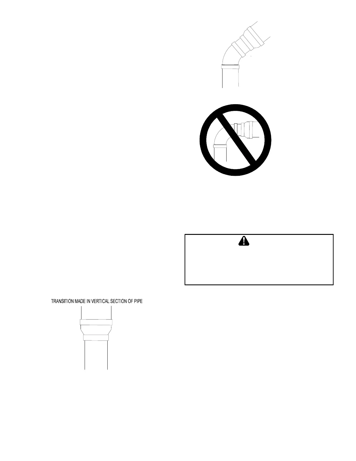
TRANSITION NO LESS
THAN 45 DEGREES TO
HORIZONTAL PLANE TO
AVOID CREATING A WATER
TRAP IN VENT PIPING.
ACCEPTABLE
NO TRANSITION ON
HORIZONTAL PLANE,
THIS CREATES A
WATER TRAP AND
RESTRICTS FLUE
GASES
Precautions must be taken to prevent condensate from
freezing inside the vent pipe. All vent piping exposed to
freezing temperatures must be insulated with 1/2” thick
closed cell foam. Inspect piping for leaks prior to installing
insulation.
T
O
AVOID
BODILY
INJURY
,
OR
EXPLOSION
,
SOLVENT
BE
KEPT
ALL
SOURCES
(
I
E
SPARKS
,
OPEN
,
AND
EXCESSIVE
HEAT
)
AS
THEY
ARE
A
VOID
VAPORS
OR
CONTACT
SKIN
AND
/
OR
EYES
Consult tables 4 & 5 to determine what diameter piping is
required for your installation. Lengths shown in the chart
apply to single pipe & two pipe installations. In a two pipe
installation the length shown refers to only one pipe, vent
or intake. Both pipes would normally be equal in length, if
dierent, then the longest pipe must be within the limits of
table 4. It is preferable to up-size from 2” to 2.5” or 3” pipe
if the pipe length & elbow count are near maximum. This
will help avoid nuisance pressure switch opening caused
by prevailing winds & sudden changes in atmospheric
pressure.
 Loading...


