33
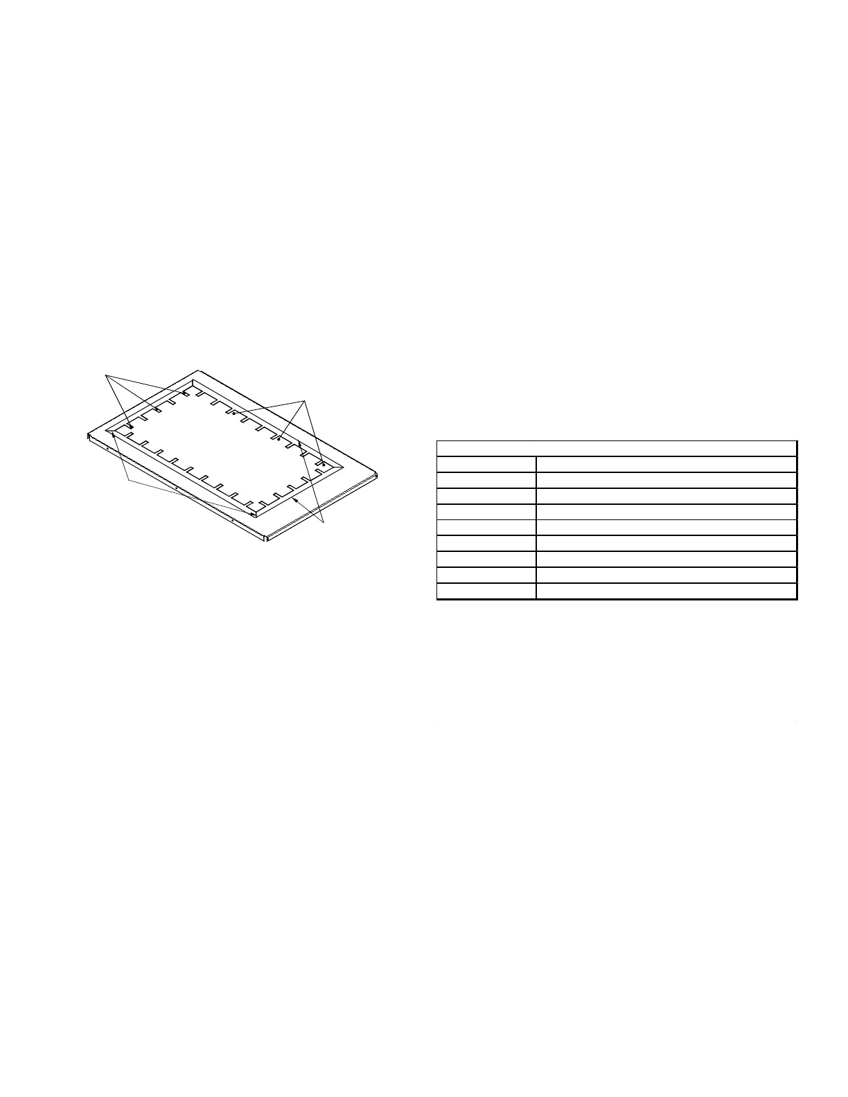
The bottom return air opening on upow models utilizes
a “lance and cut” method to remove sheet metal from the
duct opening in the base pan. To remove, simply press
out the lanced sections by hand to expose the metal strips
retaining the sheet metal over the duct opening. Using
tin snips, cut the metal strips and remove the sheet metal
covering the duct opening. In the corners of the opening,
cut the sheet metal along the scribe lines to free the duct
anges. Using the scribe line along the duct ange as a
guide, unfold the duct anges around the perimeter of the
opening using a pair of seamer pliers or seamer tongs.
CUT FOUR CORNERS
AFTER REMOVING SHEET
METAL
CUT USING TIN SNIPS
PRESS OUT BY HAND
SCRIBE LINES OUTLINING
DUCT FLANGES
When the furnace is used in connection with a cooling unit,
the furnace should be installed in parallel with or on the
upstream side of the cooling unit to avoid condensa tion
in the heating element. With a parallel ow arrange ment,
the dampers or other means used to control the ow of
air must be adequate to prevent chilled air from entering
the furnace and, if manually operated, must be equipped
with means to prevent operation of either unit unless the
damper is in the full heat or cool position.
When the furnace is installed without a cooling coil, it is
recommended that a removable access panel be provided
in the outlet air duct. This opening shall be accessible
when the furnace is installed and shall be of such a size
that the heat exchanger can be viewed for visual light
inspection or such that a sampling probe can be inserted
into the air stream. The access panel must be made to
prevent air leaks when the furnace is in operation.
When the furnace is heating, the temperature of the return
air entering the furnace must be between 55°F and 100°F.
Filters must be used with this furnace. Discuss lter
maintenance with the building owner. Filters do not ship
with this furnace, but must be provided, sized and installed
externally by the installer. Filters must comply with UL900
or CAN/ULCS111 standards. Damage or repairs due to
the installation of the furnace without lters is not covered
under the warranty.
On upow units, guide dimples locate the side return
cutout locations. Use a straight edge to scribe lines
connecting the dimples. Cut out the opening on these
lines. NOTE: An undersized opening will cause reduced
airow.
Refer to the Filter Sizing Chart to determine lter area
requirements.
Model
1 - 16 X 25 Side or 1 - 14 X 24 Bottom Return
1 - 16 X 25 Side or Bottom Return
1 - 16 X 25 Side or Bottom Return
1 - 16 X 25 Side or Bottom Return
2 - 16 X 25 Side or 1 - 20 X 25 Bottom Return
1 - 16 X 25 Side or Bottom Return
2 - 16 X 25 Side or 1 - 20 X 25 Bottom Return¹
2 - 16 X 25 Side or 1 - 24 X 24 Bottom Return¹
Larger filters may be used, filters may also be centrally located.
¹ = use 2 - 16 X 25 filters and two side returns or 20 X 25 filter on
bottom return or combination side & bottom if furnace is
connected to a cooling unit over 4 tons nominal capacity
 Loading...


