26
Turn OFF power to the furnace before installing any
accessories. Follow the humidier or air cleaner
manufacturers’ instructions for locating, mounting,
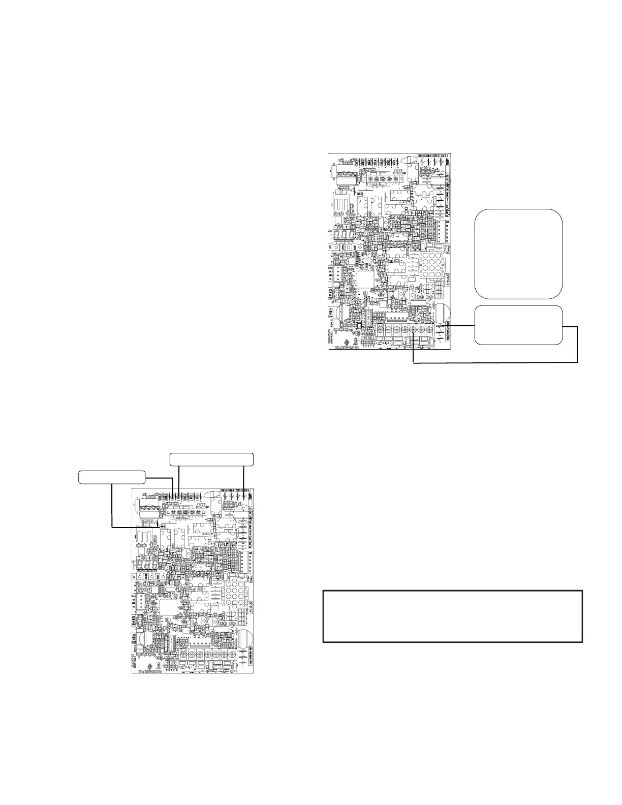
grounding, and controlling these accessories. Accessory
wiring connections are to be made through the 1/4” quick
connect terminals provided on the furnace integrated
control module. The humidier hot terminal is identied
as 120V HUM-H, its neutral terminal is identied as 120V
HUM-N. The electronic air cleaner hot terminal is identied
as EAC-H, its neutral terminal is identied as 120V
EAC-N. All eld wiring must conform to applicable codes.
Connections should be made as shown. (See Figure 32)
If it is necessary for the installer to supply additional line
voltage wiring to the inside of the furnace, the wiring
must conform to all local codes, and have a minimum
temperature rating of 105°C. All line voltage wire splices
must be made inside the furnace junction box.
The integrated control module humidier terminal 120V
HUM-H is energized with 115 volts whenever the induced
draft blower is energized. This terminal can also be used
to provide 115 volt power to a humidier transformer. The
remaining primary transformer wire would be connected
to the Line N on the control board. The integrated
control module electronic air cleaner terminals EAC-H is
energized with 115 volts whenever the circulator blower is
energized.
maintenance.
115 VAC EAC
115 VAC HUM
W R G C Y
The integrated control module single humidier terminal
“24 V HUM” is energized with 24 volts whenever the
induced draft blower is energized. Connect the common
side of the 24 volt humidier to the “C” terminal of the
thermostat terminal strip on the control board.
24 VOLT HUM. &
HUMIDISTAT
W R G C Y
24V HUM Terminal is
energized when pressure
switch is closed
Line voltage connections can be made through either the
right or left side panel. The furnace is shipped congured
for a left side electrical connection. To make electrical
connections through the opposite side of the furnace,
the junction box must be relocated to the left side prior to
making electrical connections. To relocate the junction
box, perform the following steps.
1. Remove the burner compartment door.
2. Remove and save the two screws securing the
junction box to the side panel.
3. Relocate junction box and associated plugs and
grommets to opposite side panel. Secure with
screws removed in step.
IRE NOT CIRCULATOR
OPERATION, OR ROUTINE
To ensure proper unit grounding, the ground wire should
run from the furnace ground screw located inside the
furnace junction box all the way back to the electrical
panel.
 Loading...


