39
A number of safety circuits are employed to ensure safe
and proper furnace operation. These circuits serve to
control any potential safety hazards and serve as inputs
in the monitoring and diagnosis of abnormal function.
These circuits are continuously monitored during furnace
operation by the integrated control module.
The integrated control module is an electronic device
which, if a potential safety concern is detected, will
take the necessary precautions and provide diagnostic
information through an LED.
The primary limit control is located on the partition panel
and monitors heat exchanger compartment temperatures.
It is a normally-closed (electrically), automatic reset,
temperature-activated sensor. The limit guards against
overheating as a result of insucient conditioned air
passing over the heat exchanger.
The auxiliary limit controls are located on or near the
circulator blower and monitors blower compartment
temperatures. They are a normally-closed (electrically),
manual-reset sensors. These limits guard against
overheating as a result of insucient conditioned air
passing over the heat exchanger.
The rollout limit controls are mounted on the burner/
manifold assembly and monitor the burner ame. They
are normally-closed (electrically), manual-reset sensors.
These limits guard against burner ames not being
properly drawn into the heat exchanger.
The pressure switches are normally-open (closed during
operation) negative air pressure-activated switches. They
monitor the airow (combustion air and ue products)
through the heat exchanger via pressure taps located on
the induced draft blower and the coil front cover. These
switches guard against insucient airow (combustion
air and ue products) through the heat exchanger and/or
blocked condensate drain conditions.
Temperature rise must be within the range specied on the
unit rating plate. An incorrect temperature rise may result
in condensing in or overheating of the heat exchanger.
An airow and temperature rise table is provided in the
Specication Sheet applicable to your model. Determine
and adjust temperature rise as follows:
1. Operate furnace with burners ring for approximately
ten minutes. Ensure all registers are open and all
duct dampers are in their nal (fully or partially open)
position.
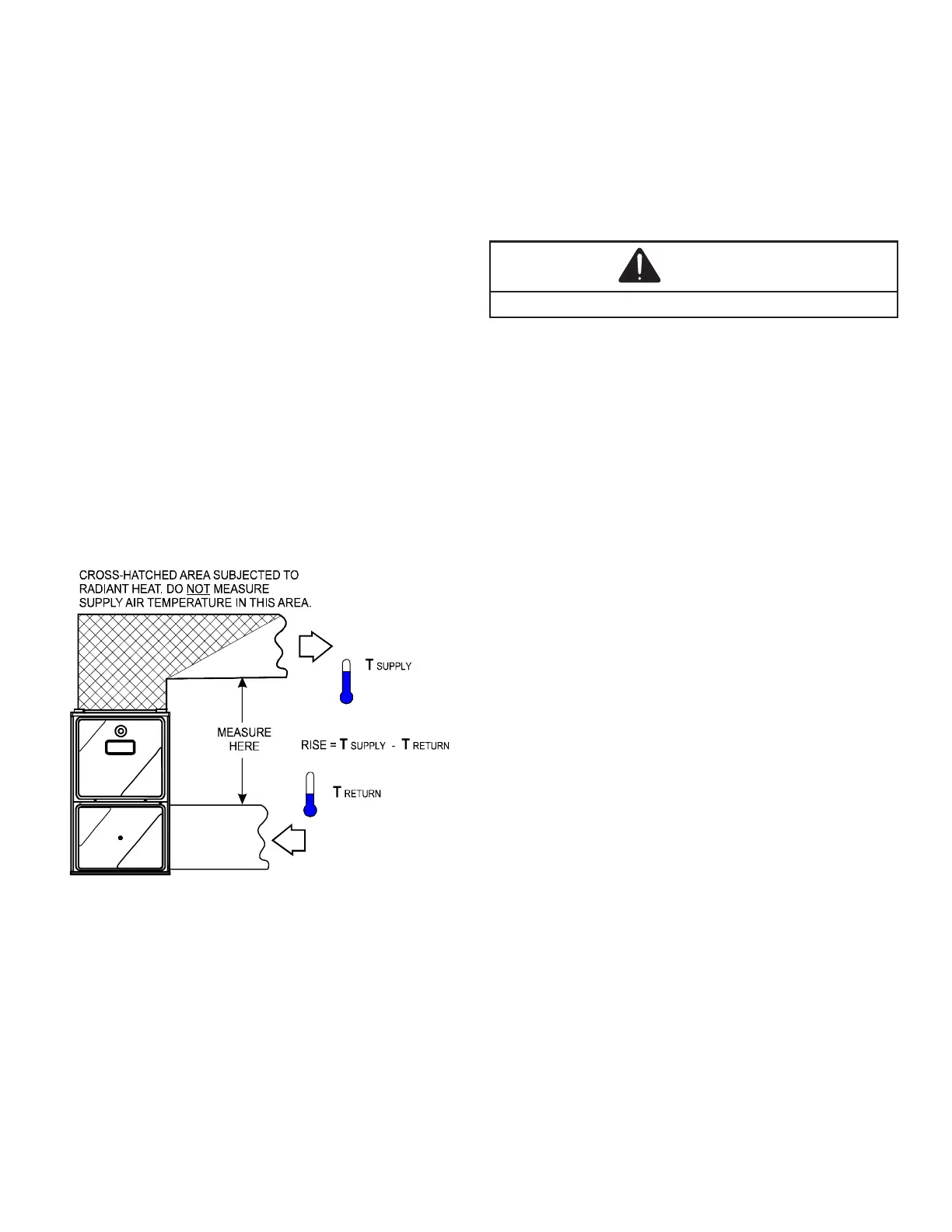
2. Place thermometers in the return and supply ducts
as close to the furnace as possible. Thermometers
must not be inuenced by radiant heat by being able
to “see” the heat exchanger.
3. Subtract the return air temperature from the supply
air temperature to determine the air temperature
rise. Allow adequate time for thermometer readings
to stabilize.
4. Adjust temperature rise by adjusting the circulator
blower speed. Increase blower speed to reduce
temperature rise. Decrease blower speed to
increase temperature rise. Refer to Startup
Procedure and Adjustment - Circulator Blower
Speeds for speed changing details.
The burner ames should be inspected with the burner
compartment door installed. Flames should be stable,
quiet, soft, and blue (dust may cause orange tips but
they must not be yellow). Flames should extend directly
outward from the burners without curling, oating, or lifting
o. Flames must not impinge on the sides of the heat
exchanger ring tubes.