30
The gas piping may enter the left or right side of the
furnace cabinet. The installer must supply rigid pipe long
enough to reach the outside of the cabinet to seal the
grommet cabinet penetration. A semi-rigid connector to the
gas piping can be used outside the cabinet per local codes.
1/2” NPT pipe and ttings are required. For models with
an “L” shaped manifold, a 4 1/2” long nipple is required.
For models with a hook shaped manifold, a 2” long nipple
is required.
A semi-rigid connector to the gas piping can be used
outside the cabinet per local codes. From the elbow, the
length of pipe and the ttings required will vary by the side
chosen, location of union and cabinet width. The union
may be placed inside or outside of the cabinet.
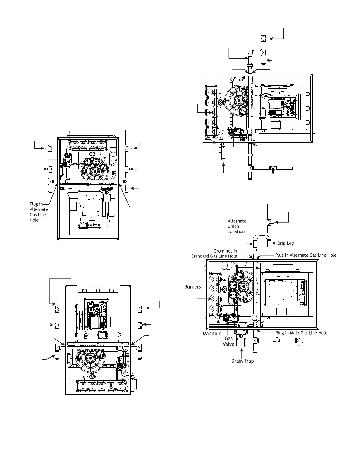
Alternate
Gas Line
Location
Gas Valve
Burners
Manual Shut Off Valve
(upstream from
ground joint
pipe union)
Drip Leg
Grommet
in Standard
Gas Line
Hole
*Ground
Joint
Pipe
Union
*Ground
Joint
Pipe
Union
*NOTE: Union may be inside furnace cabinet where allowed by local codes.
Manifold
Alternate
Gas Line
Location
Plug in
Alternate
Gas Line
Hole
Gas Valve
Burners
Manual Shut Off Valve
(upstream from ground joint pipe union)
Drip Leg
Grommet
in Standard
Gas Line
Hole
*Ground
Joint
Pipe Union
*Ground
Joint
Pipe Union
*NOTE: Union may be inside furnace cabinet where allowed by local codes.
Drip Leg
Plug in Main Gas Line Hole
Alternate
Union
Location
Manual Shut Off Valve
(upstream from
ground joint pipe union)
Gas
Valve
Burners
Drain Trap
Manifold
Plug in Alternate Gas Line Hole
Grommet in
Standard Gas Line Hole
Manual Shut Off Valve
(upstream from
ground joint
pipe union)
Before placing unit in operation, leak test the unit and gas
connections.
Check for leaks using an approved chloride-free soap and
water solution, an electronic combustible gas detector, or
other approved testing methods.

 Loading...


