32
Duct systems and register sizes must be properly
designed for the CFM and external static pressure rat ing
of the furnace. Design the ductwork in accor dance with the
recommended methods of “Air Conditioning Contractors
of America” Manual D.
Install the duct system in accordance with Standards of
the National Board of Fire Underwriters for the Installation
of Air Conditioning, Warm Air Heating and Ventilating
Systems. Pamphlets No. 90A and 90B.
A closed return duct system must be used, with the return
duct connected to the furnace. NOTE: Ductwork must
never be attached to the back of the furnace. For upow
installations requiring 1800 CFM or more, use either two
side returns or bottom return or a combination of side /
bottom. Flexible joints may be used for supply and return
con nections to reduce noise transmission. To prevent the
blower from inter fering with combustion air or draft when a
central return is used, a connecting duct must be installed
between the unit and the utility room wall. Never use a
room, closet, or alcove as a return air chamber.
Refer to your furnace rating plate for the maximum ESP
(external duct static) rating.
Total external static refers to everything external to the
furnace cabinet. Cooling coils, lters, ducts, grilles,
registers must all be considered when reading your total
external static pressure. The supply duct pressure must
be read between the furnace and the cooling coil. This
reading is usually taken by removing the “A” shaped block
o plate from the end on the coil; drilling a test hole in
it and reinstalling the block o plate. Take a duct static
reading at the test hole. Tape up the test hole after your
test is complete. The negative pressure must be read
between the lter and the furnace blower.
Too much external static pressure will result in insucient
air that can cause excessive temperature rise. This can
cause limit switch tripping and heat exchanger failure.
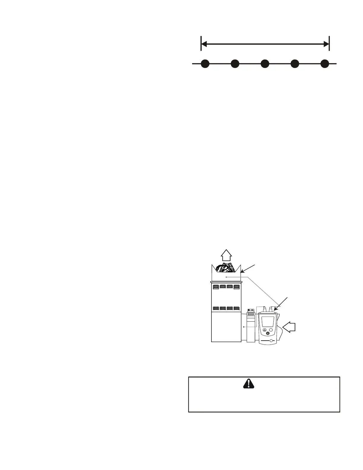
To determine total external duct static pressure, proceed
as follows;
1. With clean lters in the furnace, use a manometer to
measure the static pressure of the return duct at the
inlet of the furnace. (Negative Pressure)
2. Measure the static pressure of the supply duct.
(Positive Pressure)
3. The dierence between the two numbers is .4” w.c.
Example:
-1
0
1 2
3
Difference is 4
Static reading from return duct = -.1” w.c.
Static reading from supply duct = .3” w.c.
Total external static pressure on this system = .4” w.c.
4. Consult proper tables for the quantity of air.
If the total external static pressure exceeds the maximum
listed on the furnace rating plate, check for closed
dampers, registers, undersized and/or oversized poorly
laid out duct work.
The temperature rise of the furnace must be within the
temperature rise range listed on the furnace rating plate.
CUTAWAY OF DUCTWORK
TO EXPOSE COIL
DIGITAL
MANOMETER
RETURN
AIR
Mode
3.5
SUPPLY
AIR
E
SHEET
HOLES
BE
SHARP
SE
AS
A
PRECAUTION
SHEET
RETURN
AIR
 Loading...


