24
L
ABEL
ALL
PRIOR
TO
DISCONNECTION
CONTROLS
ERRORS
CAN
CAUSE
AND
OPERATION
PROPER
OPERATION
!
TO AVOID THE RISK ELECTRICAL SHOCK, TO
THE UNIT BE AND
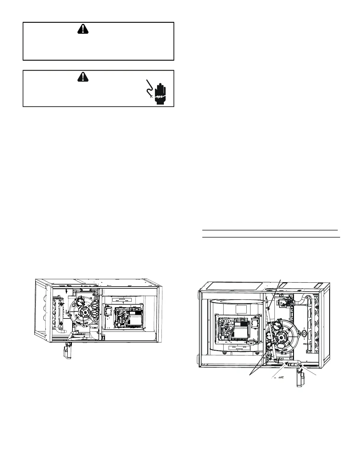
Minimum 5 1/2” clearance is required for the drain trap
beneath the furnace.
1. Remove the drain trap and factory installed drain
tube assemblies.
2. Remove two 1’’ plugs from right side of cabinet.
3. (Draining the Collector Box) From outside the
cabinet, insert the non-grommet end hose #7 into
the back drain hole and secure to collector box drain
port using a silver clamp.
4. (Draining the Vent Elbow) Insert the straight barbed
coupling into the vent - drain elbow drip leg and
secure with a red clamp.
5. From outside the cabinet, insert the non-grommet
end of hose #8 into the front cabinet drain hole and
secure on the vent - drain elbow barb tting using a
red clamp.
6. Place the drain hoses on the trap inlets and secure
with silver clamps. The outlet of the trap must face
the original bottom of furnace.
7. Using the two sheet metal screws provided in the
cabinet, secure the trap to the furnace.
8. Refer to Field Supplied Drain section for instructions
on eld supplied/installed drain on outlet of furnace
trap.
Minimum 5 1/2” clearance is required for the drain trap
beneath the furnace.
*Also see Front Cover Pressure Switch Tube Location on
page 10.
1. Remove the factory installed drain trap and hose
assemblies. Leave the 100° elbow inserted and
clamped in the vent-drain elbow.
2. Remove two 1”plugs from left side of cabinet
3. (Draining the Collector Box) Remove the cap from
the left side of the collector box drain port (bottom
in horizontal left position) and install it on right side
drain port.
4. Place radius end of hose #4 (factory installed) on
the collector box drain port and secure with a silver
clamp.
5. Insert hose #2 from outside the cabinet in the front
drain hole.
6. Connect hose #4 & hose #2 together using a straight
barbed coupling and two gold clamps (factory
installed).
7. (Draining the Vent Elbow) Remove rubber plug from
vent – drain elbow side port.
8.
Insert rubber plug removed in step 7 into the 100°
elbow. (Inserting a blunt tool such as a 3/16’’ Allen
wrench into the center of the rubber plug will stretch
the plug and allow complete insertion)
Hose #4
Hose #5
Hose #4
Hose #2
9. Place radius end of hose #4 on the side port of vent
– drain elbow and secure with a gold clamp.
10. Insert a ½” diameter PVC pipe (factory installed) into
hose #4 and secure with a gold clamp.
 Loading...


