35
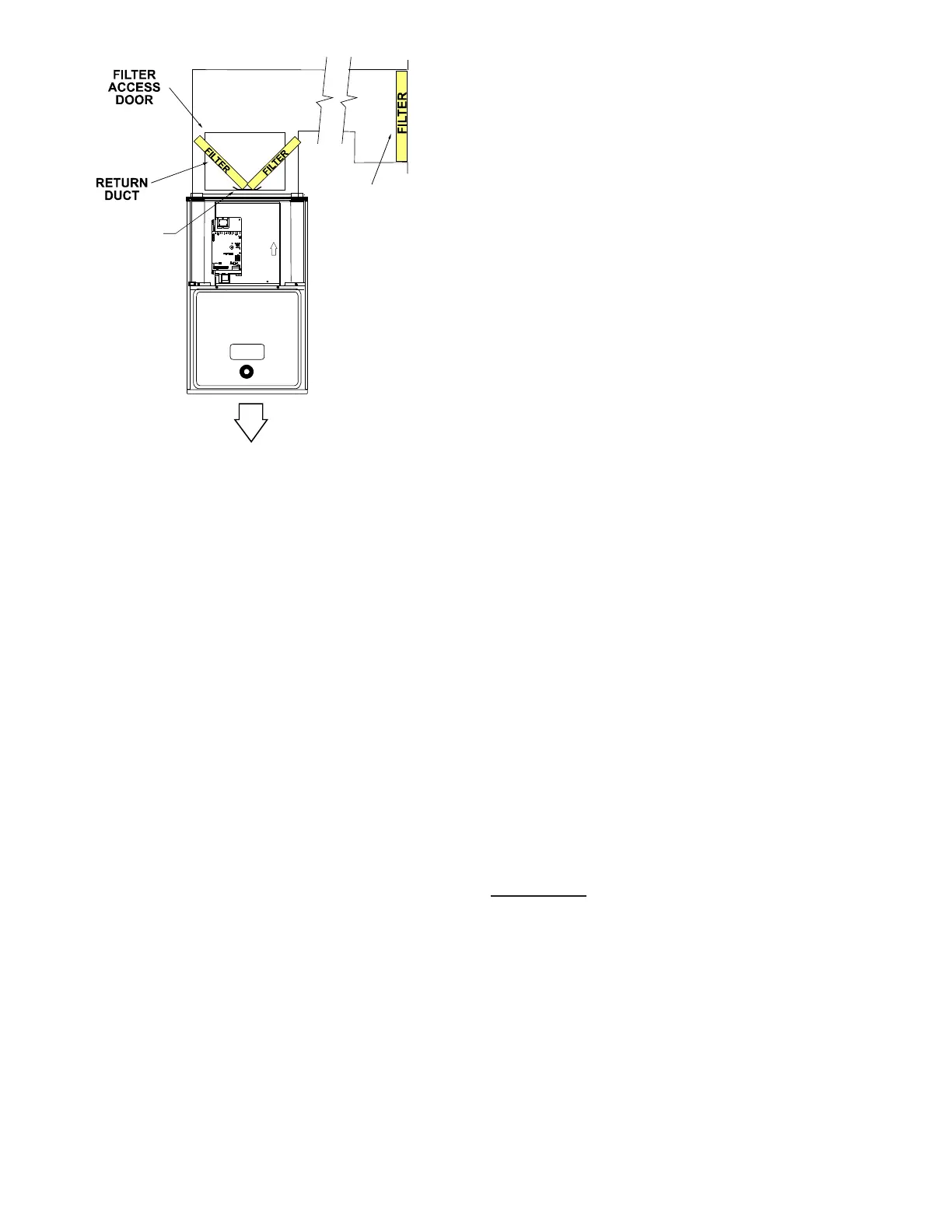
Filters must be installed in either the central return
register or in the return air duct work.
Furnace must have a 115 VAC power supply properly
connected and grounded. Proper polarity must be
maintained for correct operation. In addition to the
following start-up and adjustment items, refer to further
information in Operational Checks section.
Check that all furnace cabinet sealing components are in
place (plugs, grommets, gaskets). NOTE; If the furnace
bottom panel has not been removed for a return duct
connection, all perforations must be sealed with duct
sealant compound or other suitable method to prevent
air leakage. For optimal performance verify that all do
gaskets are properly in place and replace as needed to
prevent air
leakage.
The drain trap must be primed prior to furnace startup.
To prime, ll both sides of the drain trap with water.
This ensures proper furnace drainage upon startup and
prohibits the possibility of ue gases escaping through
the drain system.
Purge gas lines of air prior to startup. Be sure not purge
lines into an enclosed burner compartment. Follow
NFPA 54, National Fuel Gas Code 8.1 for proper purging
methods. In Canada, follow approved purging methods in
B149.1-15.
Check for leaks using an approved chloride-free soap and
water solution, an electronic combustible gas detector,
or other approved method. Verify that all required kits
(propane gas, high altitude, etc.) have been appropriately
installed.
1. Close the manual gas shuto valve external to the
furnace.
2. Turn o the electrical power to the furnace.
3. Set the room thermostat to the lowest possible
setting.
4. Remove the burner compartment door.
5. Move the furnace gas valve manual control to the
OFF position.
6. Wait ve minutes then smell for gas. Be sure check
near the oor as some types of gas are heavier than
air.
7. If you smell gas after ve minutes, immediately
follow the safety instructions in the Safety
Considerations on page 2 of this manual. If you do
not smell gas after ve minutes, move the furnace
gas valve manual control to the ON position.
8. Replace the burner compartment door.
9. Open the manual gas shuto valve external to the
furnace.
10. Turn on the electrical power to the furnace.
11. Adjust the thermostat to a setting above room
temperature.
12. After the burners are lit, set the thermostat to
desired temperature.
• On a call for heat, the thermostat contacts close & the
control board receives 24 VAC on the W terminal.
• The control board microcomputer runs its self-check
routine.
• The control veries the limit switch is closed (24 VAC
on Pin 8 of the 12 Pin connector).
• The control veries that pressure switch circuit is
open (0 VAC on Pin 5).
• The control module performs a gas valve circuitry
check to verify gas valve relay state and presence of
voltage at the valve.
• The system will energize the Induced draft blower.
• The pre-purge period begins once the pressure
switch is detected closed (24 VAC on Pin 5).
 Loading...


