8
•
If installation over a combustible oor becomes
necessary, use an accessory sub-base (see
Specication Sheet applicable for your model for
details.) A special accessory sub-base must be used
for upright counterow unit installations over any
combustible material including wood. Refer to sub-
base instructions for installation details. Follow the
instructions with the sub-base for proper installation.
Do not install the furnace directly on carpeting, tile, or
other combustible material other than wood ooring.
(NOTE: The sub-base will not be required if an air
conditioning coil is installed between the supply air
opening on the furnace and the oor.)
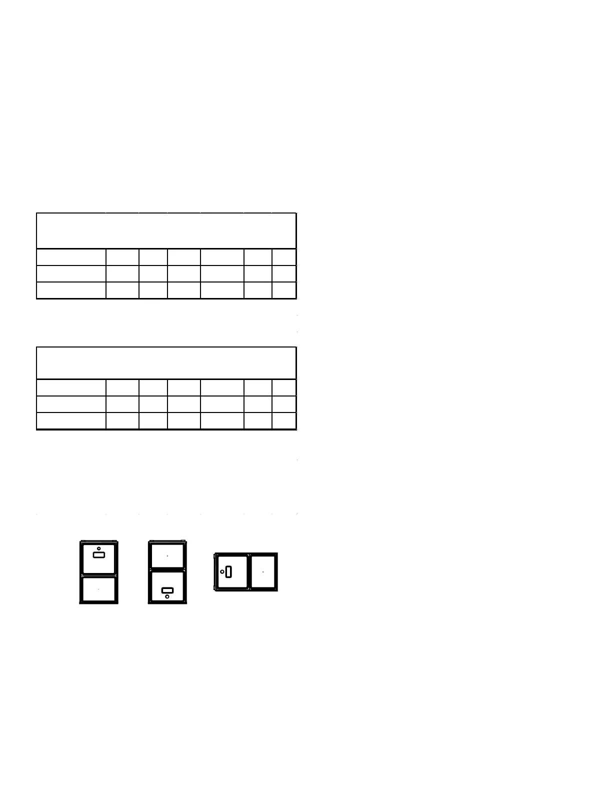
Position* Sides Rear Bottom Top
Upflow 0" 0" 3" C 0" 1"
Horizontal 6" 0" 3" C 0" 6"
DM92SN & DM96SN Minimum Clearances To
Combustible Materials (Inches)
C = If placed on combustible floor, floor MUST be
wood only.
Position* Sides Rear Bottom Top
Counterflow 0" 0" 3" NC 0" 1"
Horizontal 6" 0" 3" C 0" 6"
DC96SN Minimum Clearances To Combustible
Materials (Inches)
C = If placed on combustible floor, floor MUST be
wood only.
NC = For installations on non-combustible floors
only. A combustible subbase must be used for
installations on combustible flooring.
TOP
BOTTOM
SIDE SIDE SIDE
TOP
BOTTOM
Upflow Counterflow Horizontal
NOTES:
• For servicing or cleaning, a 24” front clearance is
required.
• Unit connections (electrical, ue and drain) may
necessitate greater clearances than the minimum
clearances listed above.
• Clearance in accordance with local installation
codes, the requirements of the gas supplier and the
manufacturer’s installation instructions.
• Dégaugement conforme aux codes d’installation
locaux, aux exigences du fournisseur de gaz et aux
instructions d’installation du fabricant.
• In all cases, accessibility clearance must take
precedence over clearances from the enclosure
where accessibility clearances are greater.
Installations must adhere to the clearances to combustible
materials to which this furnace has been design certied.
The minimum clearance information for this furnace is
provided on the unit’s clearance label. These clearances
must be permanently maintained. Clearances must
also accommodate an installation’s gas, electrical, and
drain trap and drain line connections. If the alternate
combustion air intake or vent/ue connections are used
additional clearance must be provided to accommodate
these connections. Refer to Vent/Flue Pipe and
Combustion Air Pipe for details.
A furnace installed in a conned space (i.e., a closet or utility
room) must have two ventilation openings with a total minimum
free area of 0.25 square inches per 1,000 BTU/hr of furnace
input rating. Refer to Specication Sheet applicable to your
model for minimum clearances to combustible surfaces. One
of the ventilation openings must be within 12 inches of the top;
the other opening must be within 12 inches of the bottom of
the conned space. In a typical construction, the clearance
between the door and door frame is usually adequate to
satisfy this ventilation requirement.
The following vent testing procedure is repro duced from
the
 Loading...


