4-1
4. Service and maintenance
4.1 Main components and
maintenance
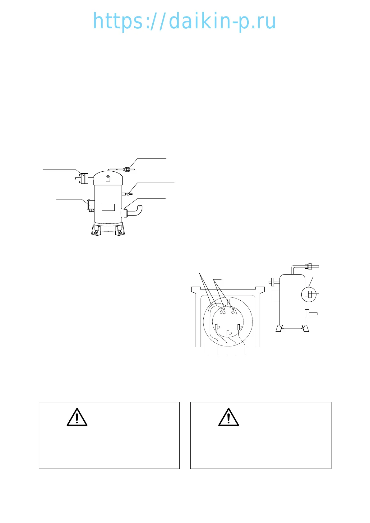
4.1.1 Scroll compressor
The compressor is of a hermetic scroll type
with the built-in motor so that there are less
places where refrigerant may leak. No
refrigerant oil is required when the unit is new
because it has been charged before delivery.
(1) Removal of compressor
q Collect the refrigerant from the quick joints on
discharge pressure regulating valve inlet and
liquid receiver outlet.
Refer to the section "4.4. Maintenance
service" on page 4-16 for refrigerant collecting
method.
w Switch off the power.
e Open the terminal box cover to disconnect
the wires.
r Remove the bolts for suction flange and
discharge flange.
t Remove the flare nut for the intermittent
injection and gauge piping.
y Remove the compressor mounting bolts.
Yellow
132
Grey
131
Red
22
White
23
Black
24
– Wire color
– Wire number
W
V
U
CTP
Lay wires on the left side
of the terminal board.
Seal with
silicon
sealant
CAUTION
The unit does not have suction stop
valve. Be sure to adhere packing tape at
suction piping section to prevent
moisture from entering.
CAUTION
The preparation of refrigerant oil is not
required.
The compressor has been charge with
the oil.
Suction flange
Discharge flange
Terminal box
Flare nut for gauge
piping
Flare nut for
injection piping
(2) Installation of compressor
q Fix the compressor base with bolts
Tightening torque: 42.7N m(435 kgf cm)
w Apply new gaskets to the suction and
discharge flange and fix them with bolts
Tightening torque for the suction flange:
25.2N m(257 kgf cm)
Tightening torque for the discharge flange:
25.2N m(257 kgf cm)
e Tighten the flare nut for intermittent injection
and gauge piping.
Tightening torque : φ6.4 : 15.7 N m
(160 kgf cm)
φ9.5 : 36.3 N m
(370 kgf cm)
r Connect wires to the terminals and put the
cover on.
Pay the utmost attention to the wiring of the
compressor. Incorrect wiring may run the
compressor in wrong direction and may cause
burn out
t Apply a silicon sealant on the flare nut section
of gauge piping.
 Loading...