EasyManuals Logo
Home>Daikin>Heat Pump>LXE10E-A14

Daikin LXE10E-A14 User Manual

Daikin LXE10E-A14
161 pages
To Next Page IconTo Next Page
To Previous Page IconTo Previous Page
Page #37 background imageLoading...
Page #37 background image
3-3
3.2 BASIC OPERATION OF ELECTRONIC CONTROLLER
3.2.1 Control panel
Name and function of each components
q
t
y
u
i
w
e
r
o
!0
Operation key
3
1
2
b
12 10 8 6 4 2
2 3 4 5 6 1
SP 5
OVER
2
INRANGE
HOURS
DAYS
1
UNDER
ALARM
R.H.
SUPPLY
RETURN
˚C / ˚F
%R H
DEFROST INRANGE DEHUMID
COMP.
˚C
˚C
SP+5
DECOS
DAIKIN ELECTRONICCONTAINER OPERATION SYSTEM
q
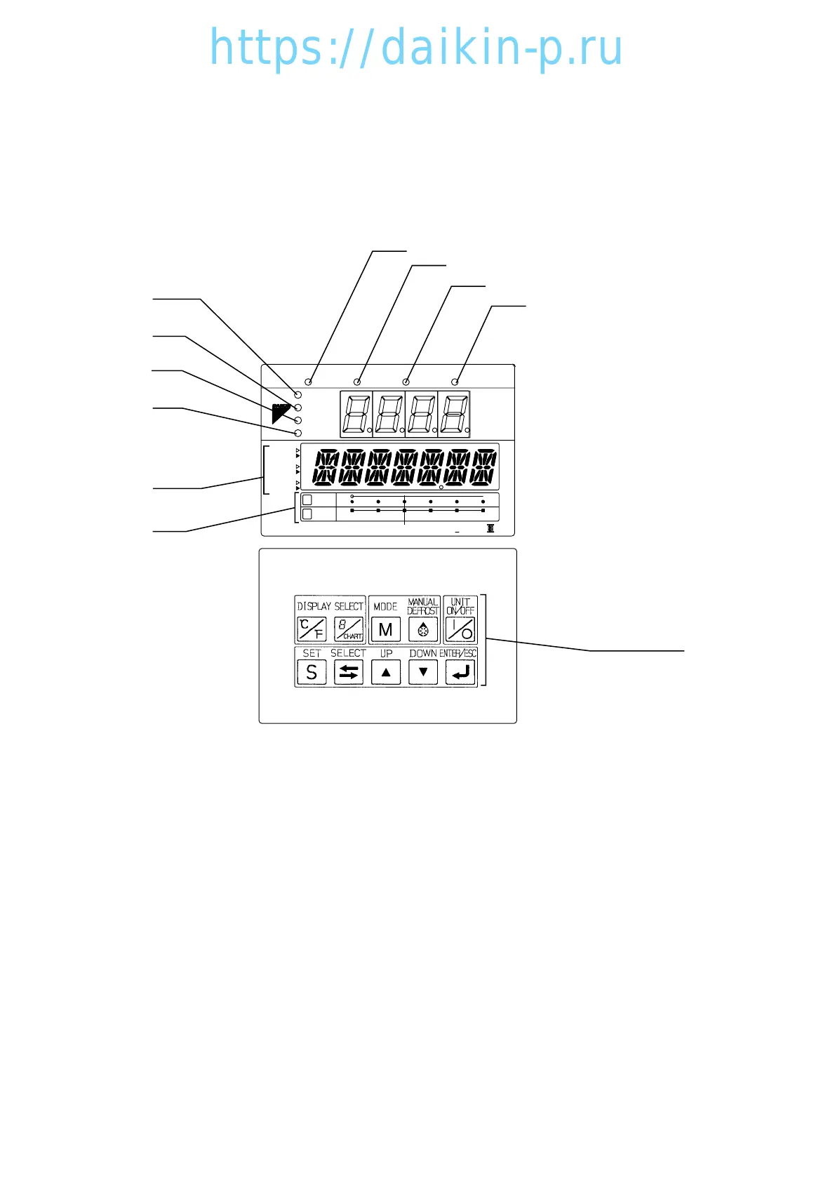
SUPPLY LED (Lights when "supply air temperature" is indicated.)
w
RETURN LED (Lights when "return air temperature" is indicated.)
e ALARM LED (Lights when alarm is generated.)
r R.H.LED (Lights when "relative humidity" is indicated.)
t COMP.LED (Lights when the compressor is running.)
y
DEFROST LED (Lights when the unit is under the defrosting operation.)
u
IN RANGE LED (Lights when the control temperature is in range.)
i DE-HUMID.LED (Lights when the controller is the
dehumidification control optional.)
o Temperature base (Used for the graphic chart indication
on the LCD.)
!0
Time base (Used for the graphic chart indication on the LCD.)
https://daikin-p.ru

Table of Contents

Questions and Answers:

Question and Answer IconNeed help?

Do you have a question about the Daikin LXE10E-A14 and is the answer not in the manual?

Daikin LXE10E-A14 Specifications

General IconGeneral
BrandDaikin
ModelLXE10E-A14
CategoryHeat Pump
LanguageEnglish

Related product manuals