4-6
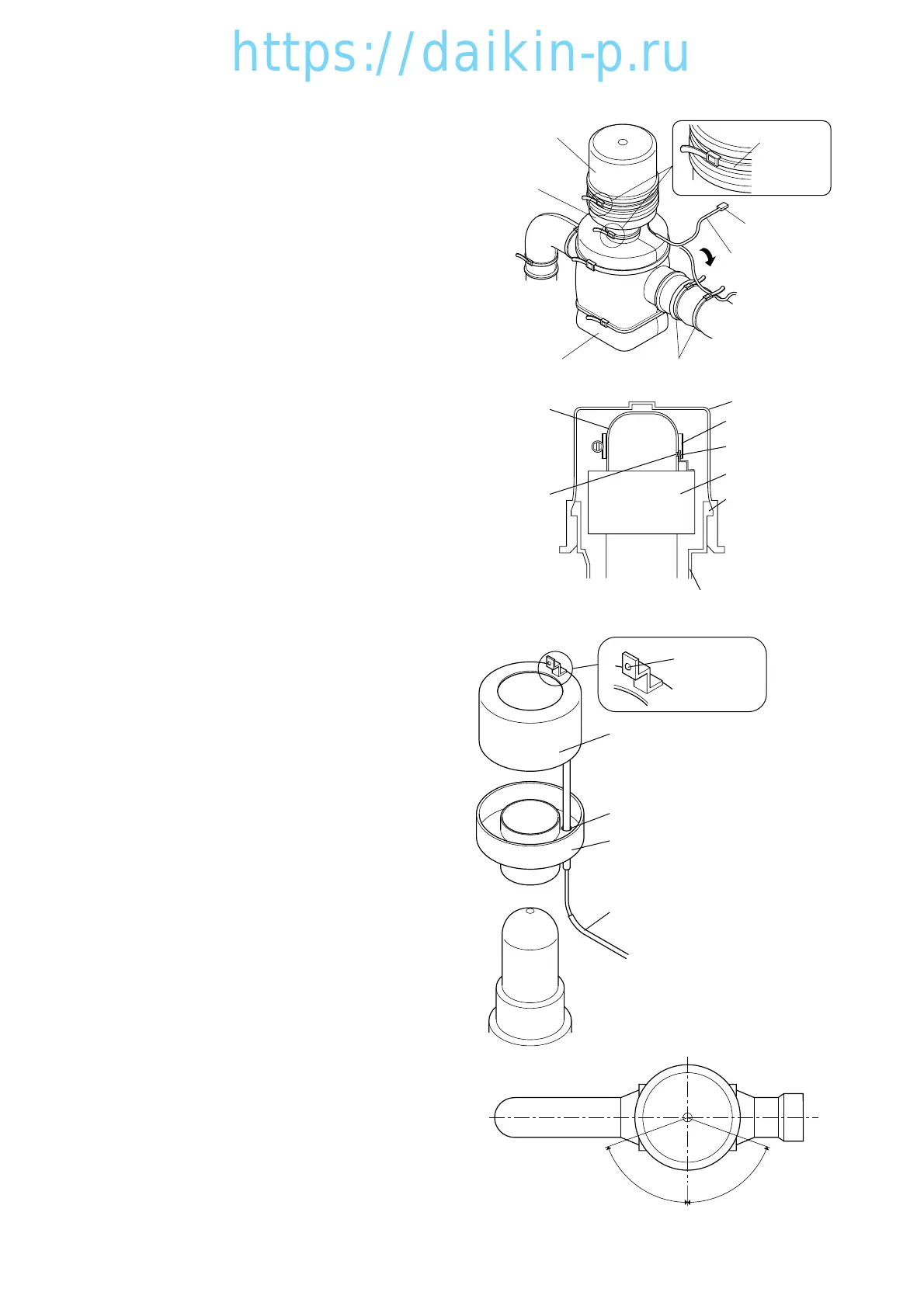
4.1.7 Suction modulation valve
The flow rate of suction gas is controlled
between 3 to 100% by a stepping motor in
order to conduct capacity control operation.
1. Replacing the coil
● Coil removing procedure
(1) Disconnect the SMV lead wire connector
q from the inside of control box.
(2) Cut the binding band e at the upper rubber cover
q and lower rubber cover w, then remove the
rubber cover q.
(3) Remove the hose band t located above the
coil r with screw driver.
(4) Remove the coil r and the lower cover
assembly w.
● Reinstalling of coil
(1) Mount the lower rubber cover assembly w and
the coil r.
Note 1) Engage the dimple i of coil bracket u
with the dimple o of coil r, and adjust
the angle.
Since the angle adjustment is important
for control of suction modulating value,
carry out the adjusting accurately.
Note 2) Set the hose band t with screw driver
Note 3)
torque is 10.05 N m(10.20.5kgf
cm).
Be careful not to set the band at an
angle.
(2) Replace the upper rubber cover q
Note) Set the engaging section of upper cover
to fit with the rim of lower rubber cover
!0
.
(3) Place the binding band e to fit the upper and
lower covers
Note 1) Fastening is 100 to 140 N
(10.2 to
14.3kgf).
Note 2) Set the buckle of lower binding band
within the range of 70˚ on the left
side and right side of the centre line at
the front of valve.
Note 3) Fix the lead wire carefully so that water
does not enter into its protecting tube
!1
. (Fix lead wire with binding band.)
(4) Connect the connector of lead wire q to the
inside of control box.
 Loading...