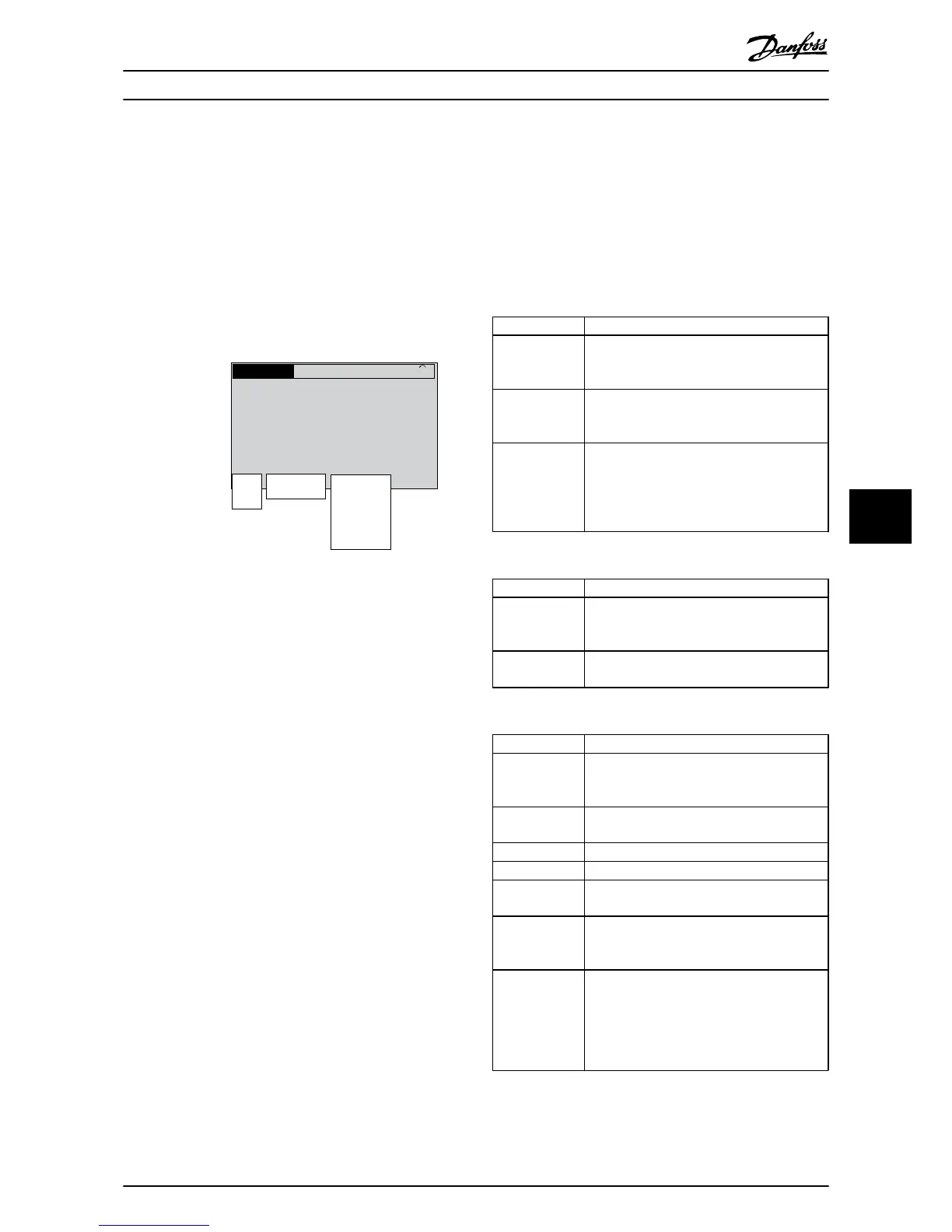
Illustration 7.1 Status Display
a. The first part of the status line indicates where
the
stop/start command originates.
b.
The second part of the status line indicates where
the speed control originates.
c. The last part of the status line gives the present
frequency converter status. These show the
operational mode the frequency converter is in.
NOTE
In auto/remote mode, the frequency converter requires
external commands to execute functions.
7.2 Status Message Definitions
The next three tables define the meaning of the status
message display words.
Operation Mode
Off The
frequency converter does not react to any
control signal until [Auto
On] or [Hand On] is
pressed.
Auto On The frequency converter is controlled from the
control terminals and/or the
serial communi-
cation.
Hand On The navigation keys on the LCP control the
frequency converter. Stop commands,
reset,
reversing, DC brake, and other signals applied
to the control terminals can override local
control.
Table 7.1 Status Message Operation Mode
Reference Site
Remote The speed reference is given from external
signals,
serial communication, or
internal
preset references.
Local The frequency converter uses [Hand On]
control or reference values
from the LCP.
Table 7.2 Status Message Reference Site
Operation Status
AC Brake
AC Brake was selected in 2-10
Brake Function.
The
AC brake over-magnetizes the motor to
achieve a controlled slow down.
AMA finish OK Automatic motor adaptation (AMA) was
carried out successfully.
AMA ready
AMA is ready to start. Press [Hand On] to start.
AMA running AMA process is in progress.
Braking The brake chopper is in operation. Generative
energy
is absorbed by the brake resistor.
Braking max. The brake chopper is in operation. The power
limit for the brake
resistor defined in
2-12 Brake Power Limit (kW) has been reached.
Coast
•
Coast inverse was selected
as a function
for a digital input (parameter group 5-1*
Digital Inputs). The corresponding terminal
is not connected.
•
Coast activated by serial communication
Status Messages
VLT
®
HVAC Drive Operating Instructions
MG11AI02 - VLT
®
is a registered Danfoss trademark
51
7 7

 Loading...