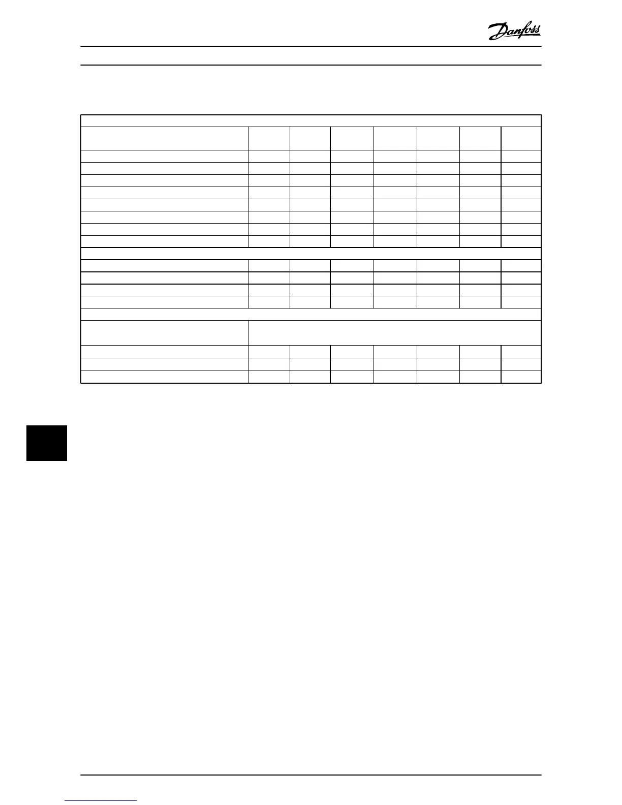
10.1.1 Mains Supply 3 x 525-690 V AC
Normal overload 110% for 1 minute
Frequency Converter
Typical
Shaft Output
[kW]
P1K1
1.1
P1K5
1.5
P2K2
2.2
P3K0
3
P4K0
4
P5K5
5.5
P7K5
7.5
Enclosure IP20 (only) A3 A3 A3 A3 A3 A3 A3
Output current
Continuous (3x525-550 V) [A] 2.1 2.7 3.9 4.9 6.1 9 11
Intermittent (3x525-550 V) [A] 2.3 3.0 4.3 5.4 6.7 9.9 12.1
Continuous kVA (3x551-690 V) [A] 1.6 2.2 3.2 4.5 5.5 7.5 10
Intermittent kVA (3x551-690 V) [A] 1.8 2.4 3.5 4.9 6.0 8.2 11
Continuous kVA 525 V AC 1.9 2.6 3.8 5.4 6.6 9 12
Continuous kVA 690 V AC 1.9 2.6 3.8 5.4 6.6 9 12
Max. input current
Continuous (3x525-550 V) [A] 1.9 2.4 3.5 4.4 5.5 8 10
Intermittent (3x525-550 V) [A] 2.1 2.6 3.8 8.4 6.0 8.8 11
Continuous kVA (3x551-690 V) [A] 1.4 2.0 2.9 4.0 4.9 6.7 9
Intermittent kVA (3x551-690 V) [A] 1.5 2.2 3.2 4.4 5.4 7.4 9.9
Additional specifications
IP20 max. cable cross section
5)
(mains, motor,
brake and
load sharing) [mm
2
]/(AWG)
[0.2-4]/(24-10)
Estimated power loss at rated max. load [W]
4)
44 60 88 120 160 220 300
Weight, enclosure IP20 [kg] 6.6 6.6 6.6 6.6 6.6 6.6 6.6
Efficiency
4)
0.96 0.96 0.96 0.96 0.96 0.96 0.96
Table 10.9 Mains Supply 3 x 525-690 V AC
Specifications
VLT
®
HVAC Drive Operating Instructions
74 MG11AI02 - VLT
®
is a registered Danfoss trademark
1010

 Loading...