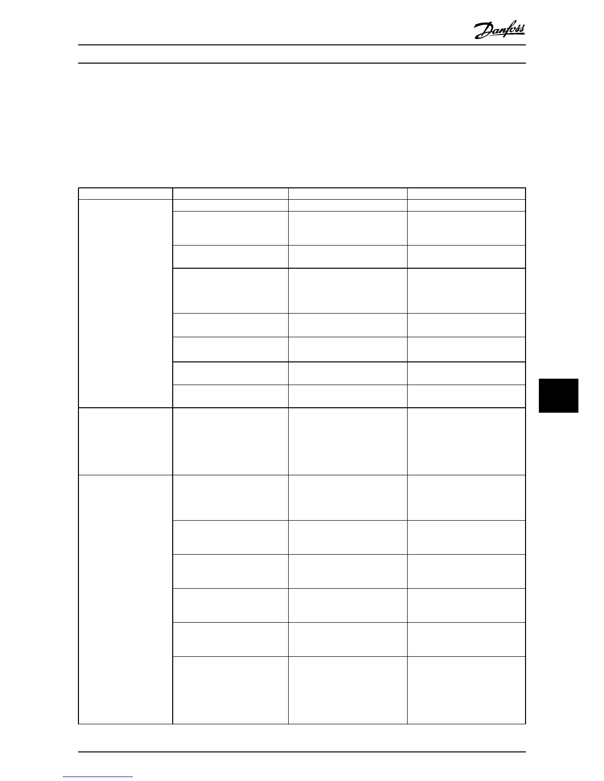
9 Basic Troubleshooting
9.1 Start Up and Operation
Symptom Possible cause Test Solution
Display dark/No function
Missing input power
See Table 3.1
Check the input
power source
Missing or open fuses or circuit
breaker tripped
See open
fuses and tripped circuit
breaker in this table for possible
causes
Follow the recommendations
provided
No power to the LCP Check the LCP cable for proper
connection or damage
Replace
the faulty LCP or
connection cable
Shortcut on control voltage
(terminal 12 or
50) or at control
terminals
Check the 24 V control voltage
supply for terminals 12/13 to 20-39
or 10 V supply for terminals 50 to
55
Wire the terminals properly
Wrong LCP (LCP from VLT
®
2800
or 5000/6000/8000/ FCD
or FCM)
Use only LCP 101 (P/N 130B1124)
or LCP 102
(P/N 130B1107)
Wrong contrast setting
Press [Status] + [
▲
]/[
▼
]
to adjust
the
contrast
Display (LCP) is defective Test using a different LCP Replace the faulty LCP or
connection
cable
Internal voltage
supply fault or
SMPS is defective
Contact
supplier
Intermittent display
Overloaded power supply (SMPS)
due to improper
control wiring or
a fault within the frequency
converter
To rule out a problem in the
control wiring, disconnect all
control wiring by removing the
terminal blocks.
If the display stays lit, then the
problem is in the control wiring.
Check the wiring for shorts or
incorrect connections. If the display
continues to cut out, follow the
procedure for display dark.
Motor not running
Service switch open or missing
motor
connection
Check if
the motor is connected
and the connection is not
interrupted (by a service switch or
other device).
Connect the motor and check the
service switch
No mains power with 24 V DC
option card
If the
display is functioning but no
output, check that mains power is
applied to the frequency converter.
Apply mains power to run the unit
LCP Stop Check if [Off] has been pressed Press [Auto On] or [Hand On]
(depending on operation
mode) to
run the motor
Missing start signal (Standby)
Check 5-10 Terminal 18 Digital Input
for correct setting
for terminal 18
(use default setting)
Apply a valid start signal to start
the motor
Motor coast signal active
(Coasting)
Check 5-12 Coast inv. for correct
setting for terminal
27 (use default
setting)..
Apply 24 V on terminal 27 or
program this terminal to No
operation
Wrong reference signal source Check reference signal: Local,
remote or bus
reference? Preset
reference active? Terminal
connection correct? Scaling of
terminals correct? Reference signal
available?
Program correct settings. Check
3-13 Reference Site. Set preset
reference active in parameter
group 3-1* References. Check for
correct wiring. Check scaling of
terminals. Check reference signal.
Basic Troubleshooting
VLT
®
HVAC Drive Operating Instructions
MG11AI02 - VLT
®
is a registered Danfoss trademark
63
9 9

 Loading...