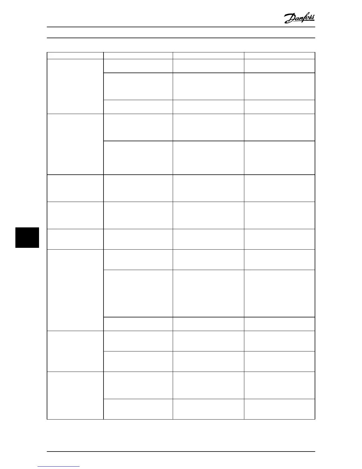
Symptom Possible cause Test Solution
Motor running in wrong
direction
Motor rotation limit
Check that 4-10 Motor Speed
Direction is
programmed correctly.
Program correct settings
Active reversing signal Check if a reversing command is
programmed for the terminal
in
parameter group 5-1* Digital
inputs..
Deactivate reversing signal
Wrong motor phase connection
See 3.7 Check Motor Rotation in
this manual
Motor is
not reaching
maximum speed
Frequency limits set wrong
Check output limits in 4-13 Motor
Speed High Limit
[RPM], 4-14 Motor
Speed High Limit [Hz] and 4-19 Max
Output Frequency.
Program correct limits
Reference input signal not scaled
correctly
Check reference input signal
scaling in 6-0* Analog
I/O Mode and
parameter group 3-1* References.
Reference limits in parameter
group 3-0* Reference Limit.
Program correct settings
Motor speed unstable
Possible incorrect parameter
settings
Check the settings of all motor
parameters, including all motor
compensation
settings. For closed
loop operation, check PID settings.
Check settings in parameter group
1-6* Analog I/O mode. For closed
loop operation, check settings in
parameter group 20-0* Feedback..
Motor runs rough
Possible over-magnetization Check for incorrect motor settings
in all motor parameters
Check
motor settings in parameter
groups 1-2* Motor Data, 1-3* Adv
Motor Data, and 1-5* Load Indep.
Setting.
Motor will not brake
Possible incorrect settings in the
brake parameters. Possible too
short
ramp down times
Check brake parameters. Check
ramp time settings
Check parameter group 2-0* DC
Brake and 3-0* Reference Limits.
Open power fuses or circuit
breaker trip
Phase to phase
short Motor or panel has a short phase
to phase. Check motor
and panel
phase for shorts
Eliminate any shorts detected
Motor overload Motor is overloaded for the
application
Perform startup test and verify
motor current is within
specifi-
cations. If motor current is
exceeding nameplate full load
current, motor may run only with
reduced load. Review the specifi-
cations for the application.
Loose connections Perform pre-startup check for loose
connections
Tighten loose connections
Mains current imbalance
greater than 3%
Problem with
mains power (See
Alarm 4 Mains phase
loss
description)
Rotate input power leads into the
frequency converter one position: A
to B, B to C, C to A.
If imbalanced leg follows the wire,
it is a power problem. Check mains
power supply.
Problem with the frequency
converter
Rotate input power leads into the
frequency converter one position:
A
to B, B to C, C to A.
If imbalance leg stays on same
input terminal, it is a problem with
the unit. Contact the supplier.
Motor current imbalance
greater than 3%
Problem with motor or motor
wiring
Rotate output motor leads one
position: U to V,
V to W, W to U.
If imbalanced leg follows the wire,
the problem is in the motor or
motor wiring. Check motor and
motor wiring.
Problem with the frequency
converters
Rotate output motor leads one
position: U to V,
V to W, W to U.
If imbalance leg stays on same
output terminal, it is a problem
with the unit. Contact the supplier.
Basic Troubleshooting
VLT
®
HVAC Drive Operating Instructions
64 MG11AI02 - VLT
®
is a registered Danfoss trademark
99

 Loading...