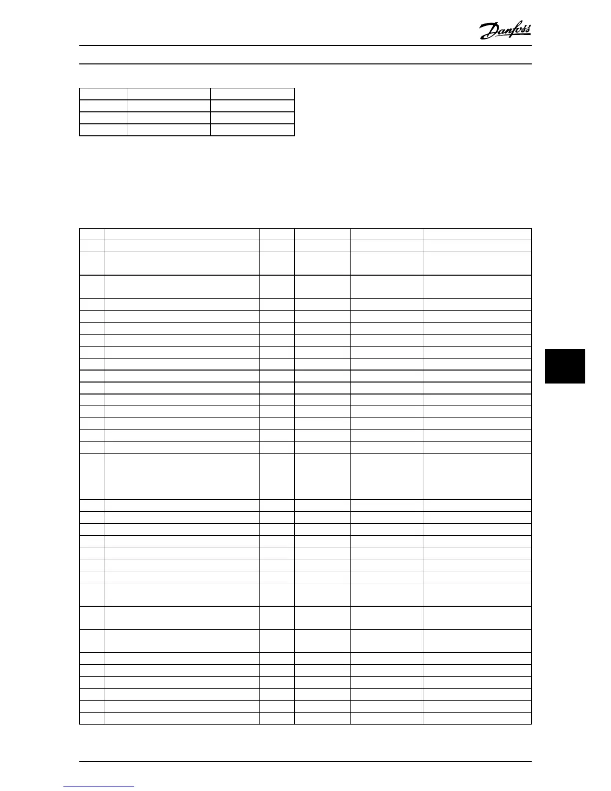
Warning LED Alarm LED
Warning On Off
Alarm Off On (Flashing)
Trip-Lock On On (Flashing)
Table 8.1 Status Indicator Lights Explanations
8.4 Warning and Alarm Definitions
Table 8.2
defines whether a warning is issued before an alarm, and whether the alarm trips the unit or trip locks the unit.
No. Description Warning Alarm/Trip Alarm/Trip
Lock Parameter Reference
1 10 Volts low X
2 Live zero error (X) (X) 6-01 Live Zero Timeout
Function
4 Mains phase loss (X) (X) (X) 14-12 Function at Mains
Imbalance
5 DC link voltage high X
6 DC link voltage low X
7 DC over voltage X X
8 DC under voltage X X
9 Inverter overloaded X X
10 Motor ETR over temperature (X) (X) 1-90 Motor Thermal Protection
11 Motor thermistor over temperature (X) (X) 1-90 Motor Thermal Protection
12 Torque limit X X
13 Over Current X X X
14 Earth (Ground) fault X X X
15 Hardware mismatch X X
16 Short Circuit X X
17 Control word timeout (X) (X) 8-04 Control Timeout Function
18 Start Failed X 1-77 Compressor Start Max
Speed
[RPM],
1-79
Compressor
Start Max Time to Trip,
1-03 Torque Characteristics
23 Internal Fan Fault X
24 External Fan Fault X 14-53 Fan Monitor
25 Brake resistor short-circuited X
26 Brake resistor power limit (X) (X) 2-13 Brake Power Monitoring
27 Brake chopper short-circuited X X
28 Brake check (X) (X) 2-15 Brake Check
29 Drive over temperature X X X
30 Motor phase U missing (X) (X) (X) 4-58 Missing Motor Phase
Function
31 Motor phase V missing (X) (X) (X) 4-58 Missing Motor Phase
Function
32 Motor phase W missing (X) (X) (X) 4-58 Missing Motor Phase
Function
33 Inrush fault X X
34 Fieldbus communication fault X X
35 Out of frequency range X X
36 Mains failure X X
37 Phase Imbalance X X
38 Internal fault X X
Warnings and Alarms
VLT
®
HVAC Drive Operating Instructions
MG11AI02 - VLT
®
is a registered Danfoss trademark
55
8 8

 Loading...