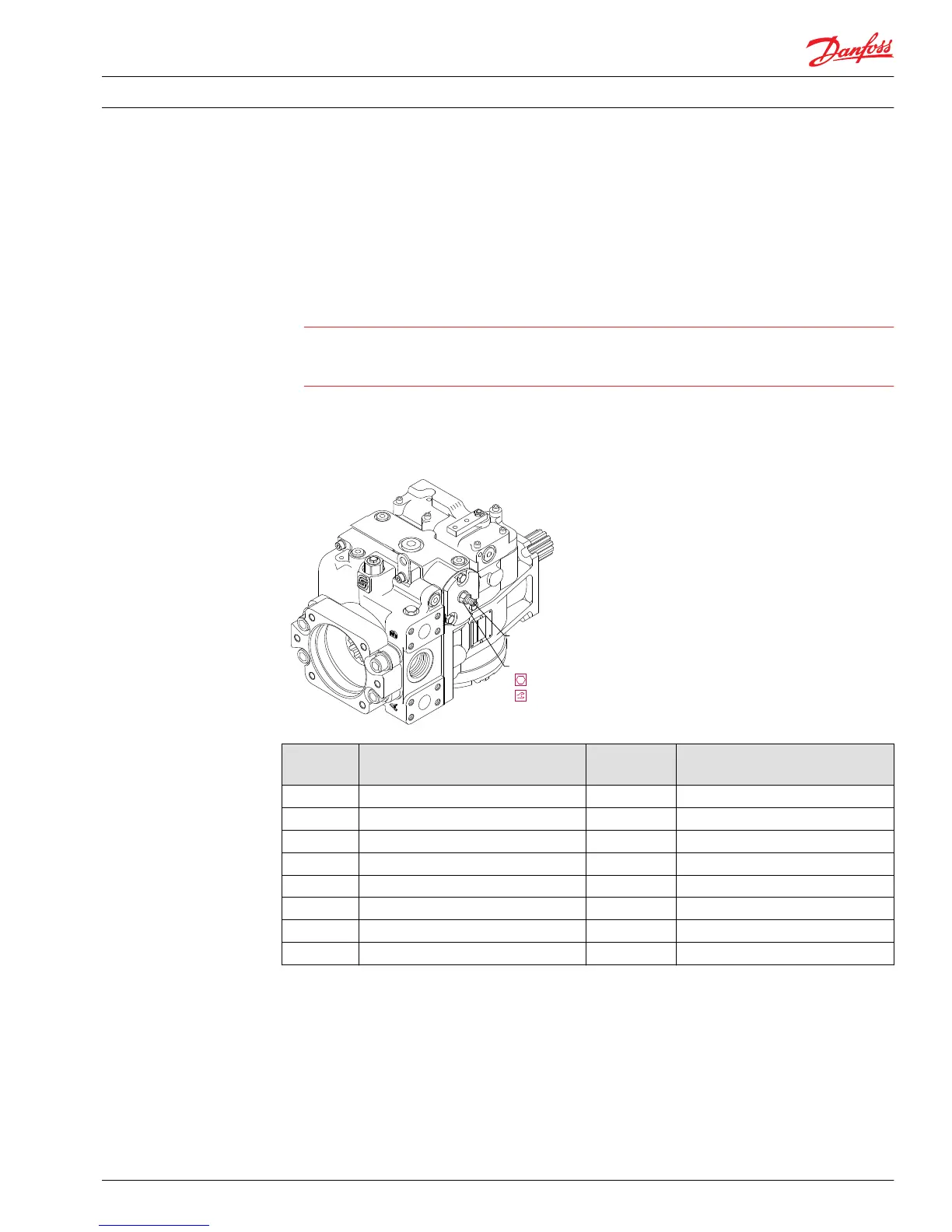
Displacement limiter adjustment
You can limit the maximum displacement in either direction.
1. Loosen the lock nut (F212) while holding the adjusting screw (F213) steady.
2. Rotate the adjusting screw some amount (using information in the following table). Rotating the
adjusting screw clockwise decreases the maximum displacement of the pump while rotating the
adjusting screw counterclockwise increases the maximum displacement.
Caution
Take care in adjusting displacement limiters to avoid undesirable flow or speed conditions. Re-torque
lock nut (F212) after every adjustment to prevent an unexpected change in operating conditions and
to prevent external leakage during unit operation.
3. One turn of the adjusting screw changes the maximum displacement as shown in table below
4. After establishing the desired maximum displacement setting, torque the lock nut to the torque
shown in table below.
Displacement limiter adjustment
Frame size Lock nut wrench size and torque Adjusting
screw size
Approximate displacement change
per revolution of adjusting screw
030 13 mm 24 N•m [18 lbf•ft] 4 mm 2.8 cm³/(rev) [0.17 in³/rev]
042 13 mm 24 N•m [18 lbf•ft] 4 mm 3.5 cm³/(rev) [0.21 in³/rev]
055 13 mm 24 N•m [18 lbf•ft] 4 mm 4.2 cm³/rev [0.26 in³/rev]
075 13 mm 24 N•m [18 lbf•ft] 4 mm 5.1 cm³/rev [0.31 in³/rev]
100 13 mm 24 N•m [18 lbf•ft] 4 mm 6.2 cm³/rev [0.38 in³/rev]
130 17 mm 48 N•m [35 lbf•ft] 5 mm 8.8 cm³/rev [0.53 in³/rev]
180 19 mm 125 N•m [92 lbf•ft] 6 mm 12.5 cm³/rev [0.76 in³/rev]
250 19 mm 125 N•m [92 lbf•ft] 6 mm 17.3 cm³/rev [1.06 in³/rev]
Standard manual displacement control (MDC) adjustment
There are no adjustable elements in the manual displacement control. Centering springs and washers on
each end of the control spool hold it in its neutral position. Since there is no centering spring on the
control input shaft, the shaft automatically assumes the appropriate position when the control is installed
on the pump.
Service Manual
Series 90 Pumps
Adjustments
520L0818 • Rev 0101 • August 2015 33

 Loading...