2. The orifice check valve is located in the control assembly, at the surface of the pump housing face.
Remove the spring retainer and spring from the orifice check valve cavity and then remove the orifice
check valve.
3. Clean and install the orifice check valve in the cavity and then install the spring and spring retainer to
hold the orifice check valve in position.
4. Assemble the control onto the pump. Refer to the instructions for the specific control.
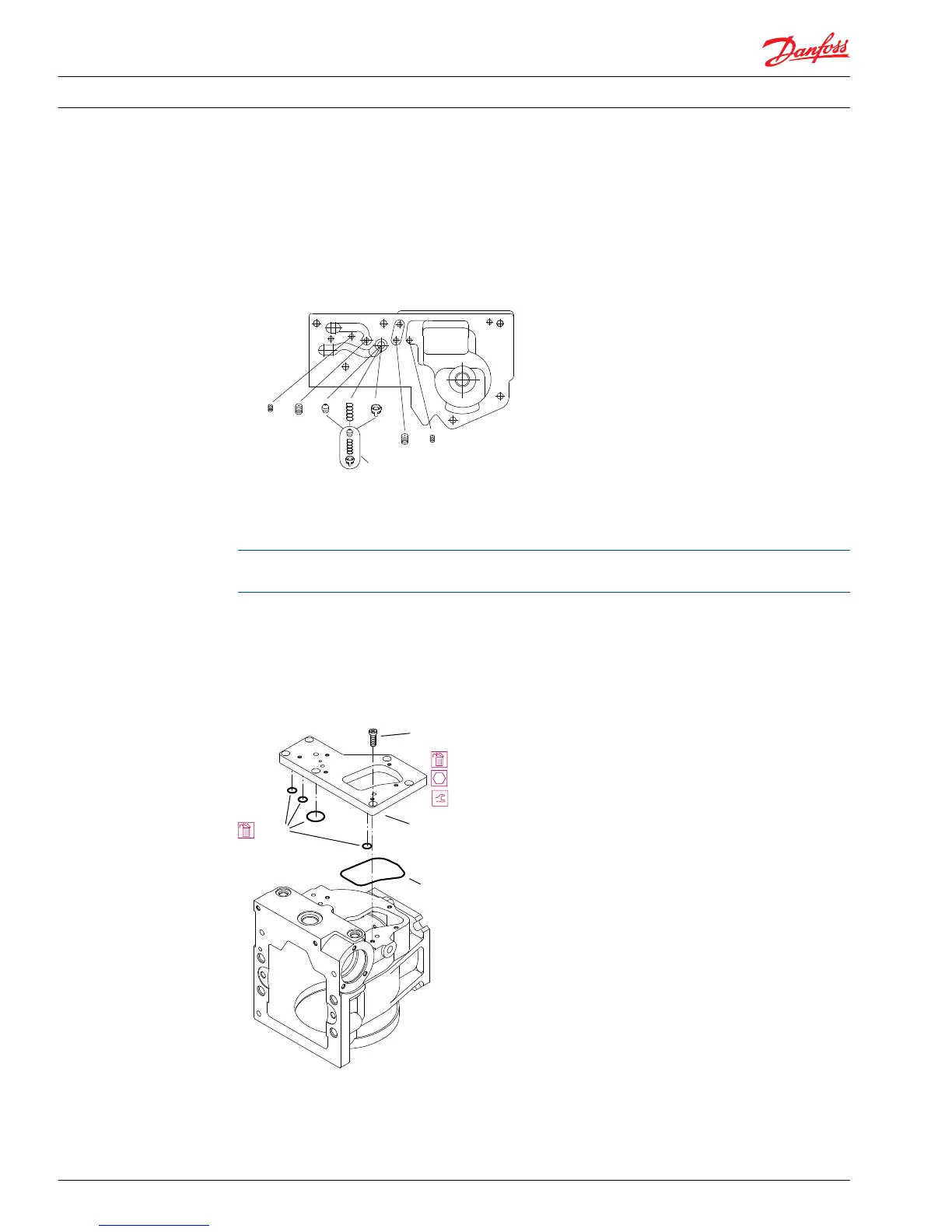
Underside of an MDC module showing orifice locations
Displacement control adapter plate (early production 130 pumps only)
Do not remove the adapter plate unless leakage is evident. The mounting screws with sealing compound
are difficult to remove.
The screws fastening the control adapter plate to the housing have sealing compound on the threads.
You may remove them with a 6 mm internal hex wrench if necessary. Remove and discard the O-rings
and seals.
When installing the adapter plate, replace screws (with sealing compound), and ensure the new O-rings
and seal are in the proper position. Torque the screws to 32 N•m [24 lbf•ft].
Displacement control adapter plate (early production 130 cm³ pumps only)

 Loading...