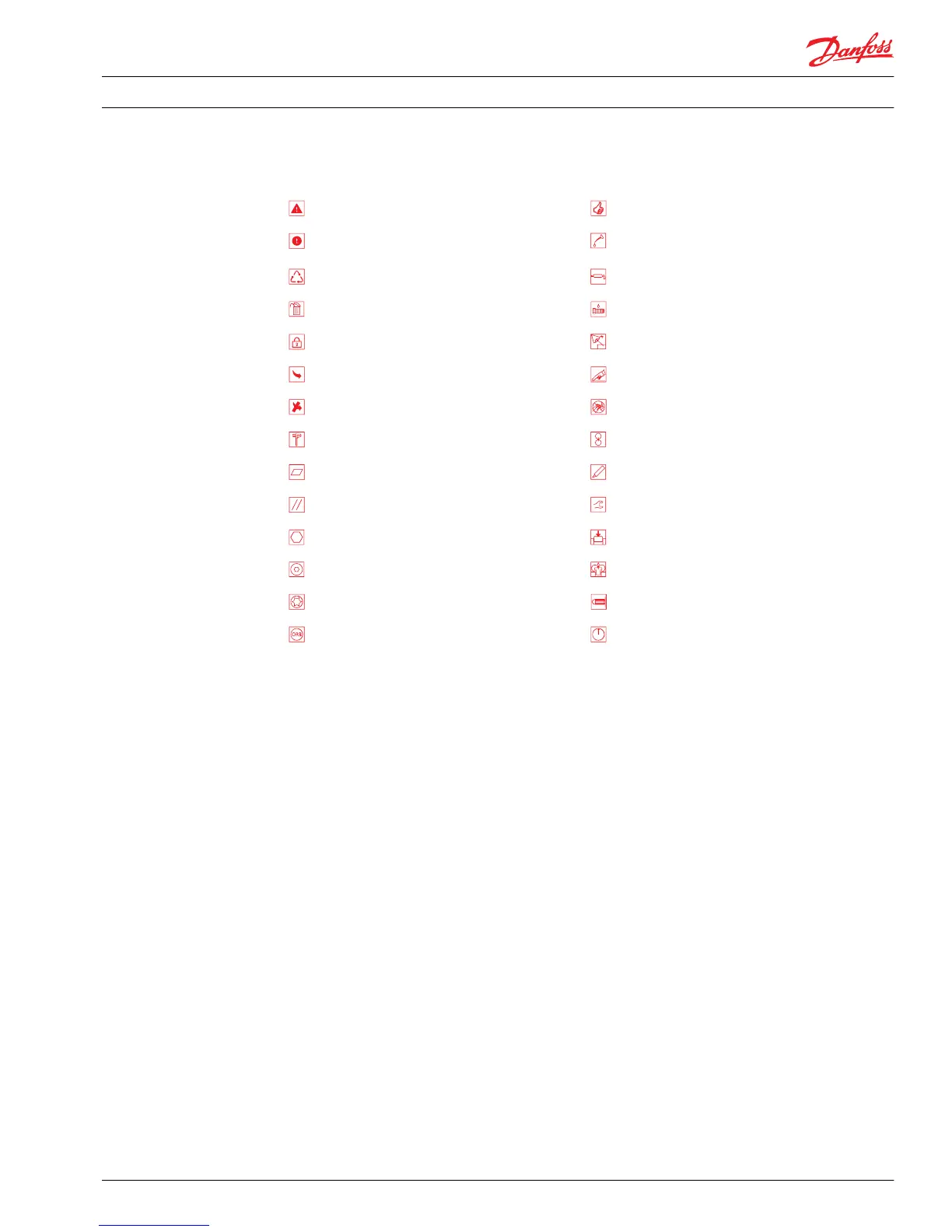
Symbols used in Danfoss literature
WARNING may result in injury Tip, helpful suggestion
CAUTION may result in damage to product or
property
Lubricate with hydraulic fluid
Reusable part Apply grease / petroleum jelly
Non-reusable part, use a new part Apply locking compound
Non-removable item Inspect for wear or damage
Option - either part may exist Clean area or part
Superseded - parts are not interchangeable Be careful not to scratch or damage
Measurement required Note correct orientation
Flatness specification Mark orientation for reinstallation
Parallelism specification Torque specification
External hex head Press in - press fit
Internal hex head Pull out with tool – press fit
Torx head Cover splines with installation sleeve
O-ring boss port Pressure measurement/gauge location or
specification
The symbols above appear in the illustrations and text of this manual. They are intended to communicate
helpful information at the point where it is most useful to the reader. In most instances, the appearance
of the symbol itself denotes its meaning. The legend above defines each symbol and explains its purpose.
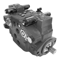
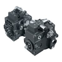
Design
Danfoss Series 90 closed circuit piston pumps convert input torque into hydraulic power. The input shaft
transmits rotational force to the cylinder block. Bearings support the input shaft at the front and rear of
the pump. The shaft is splined into the cylinder block. A lip-seal at the front end of the pump prevents
leakage where the shaft exits the pump housing. The spinning cylinder block contains nine reciprocating
pistons. A ball joint at one end connects each piston to a brass slipper. Fixed-clearance hold-down
brackets keep the slippers in contact with the swashplate. The reciprocating movement of the pistons
occurs as the slippers slide against the inclined swashplate during rotation. The valve plate connects one
half of the cylinder block to low pressure and the other half to high pressure. As each piston cycles in and
out of its bore, fluid is drawn from the inlet and displaced to the outlet thereby imparting hydraulic
power into the system. A small amount of fluid flows from the cylinder block/valve plate and slipper/
swashplate interfaces for lubrication and cooling. Case drain ports return this fluid to the reservoir.
The angle of the swashplate controls the volume of fluid displaced into the system. The servo piston
forces the swashplate into an inclined position. The pump control, acting on input from the operator, by
modulating pressure balance across the servo piston, sets displacement in the system circuit.
Service Manual
Series 90 Pumps
Introduction
520L0818 • Rev 0101 • August 2015 7

 Loading...