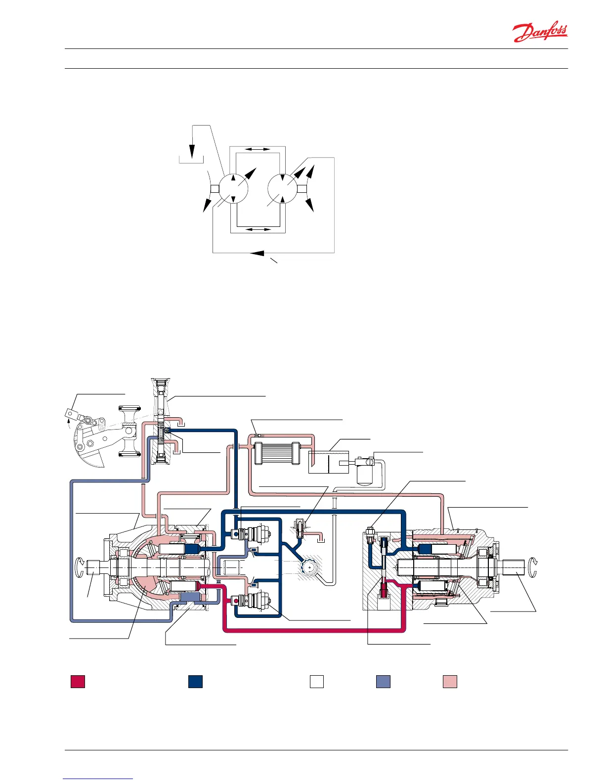
Basic closed circuit diagram
Input
PV
MF
Case drain line
Output
Flow (Bi-directional)
Reservoir
P104 120E
Case drain and heat exchanger
The pump and motor require case drain lines to remove hot fluid from the system. The topmost port
drains the motor to ensure the case remains full of fluid. Fluid routes through the lower drain port on the
pump and out the topmost port to the reservoir. A heat exchanger, with a bypass valve, cools the case
drain fluid before it returns to the reservoir.
System circuit diagram
Pump Motor
Working loop (low pressure)
Control fluid
Suction line
Case drain fluid
Working loop (high pressure)
Motor swashplate
Loop flushing valve
Displacement control valve
Heat exchanger bypass valve
Reservoir
Vacuum gauge
Purge relief valve
Fixed displacement motor
Output shaft
Multi-function valve
Charge pump
To
pump
case
Servo
pressure
relief valves
Servo control cylinder
Pump swashplate
Input shaft
Reversible variable
displacement pump
Servo control cylinder
Heat exchanger
Multi-function valve
Charge pressure relief valve
Orificed check
valve
Control handle
P102 000
Service Manual Series 90 Pumps
Introduction
520L0818 • Rev 0101 • August 2015 9

 Loading...