1.
2.
3.
4.
5.
6.
Figure 10: Defrost start
Network:
The defrost start signal is received from a system manager via data communication.
Adaptive defrost:
Here defrosting is started based on intelligent registering of evaporator performance.
Max. thermostat runtime:
When the aggregate time has passed a preset value, a defrost will be initiated.
Manual:
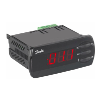
An extra defrost can be activated from the defrost button on the AK-UI55 Set display (though, not with application
5) or via a parameter setting. All the mentioned methods can be used in parallel – if just one of them is activated, a
defrost will be started.
Stop of defrost
Defrosting can be stopped by either:
• Time
• Temperature with one or two defrost termination sensors (with time as safety)
Compressor run during hot gas defrost
If the defrosting method is set to “Gas,” the compressor will be “On” during the defrost cycle. (Only for application
situations that include a compressor output).
Fans
The fans can be stopped or operated during defrosting. They can also run and then be stopped at a set temperature.
The temperature signal is obtained from the defrost stop sensor.
Defrost sequence
Pump down
Defrost
Waiting position after defrost
Draining (drain delay. Hot gas only)
Drip o
Delay of fan
Real-time clock
The controller has a built-in real-time clock which can be used to start defrosts. This clock has a power reserve of
four days.
If the controller is equipped with data communication, the clock will automatically be updated from a Danfoss
system manager.
Coordinated defrost
There are two ways in which coordinated defrost can be arranged.
© Danfoss | Climate Solutions | 2021.02 BC364229688105en-000101 | 13
AK-CC55 Single Coil and Single Coil UI
 Loading...
