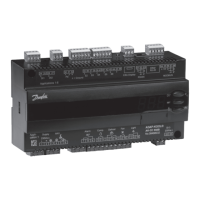
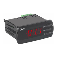
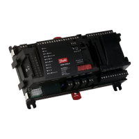
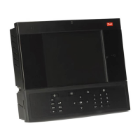
AK-CC55 connect menu (SW ver. 1.5x)
Start / Stop
Table 27: Start/Stop
Start / stop of refrigeration. With this setting refrigera-
tion can be started, stopped or a manual override of
the outputs can be allowed. (For manual control the
value is set at -1). Then the outputs can be force con-
trolled. Start / stop of refrigeration can also be accom-
plished with the external switch function connected
to a DI input.Stopped control will give a ”Main switch
OFF" alarm.
-1=Manual, 0=Stop, 1=Start
Delay of outputs at
power-up
Delay of output signal after start-up After start-up or
a power failure the controller’s functions can be de-
layed so that overloading of the electricity supply
network is avoided. Here you can set the time delay.
Conguration
Table 28: Conguration
Start / stop of refrigeration. With this setting refrigera-
tion can be started, stopped or a manual override of
the outputs can be allowed. (For manual control the
value is set at -1). Then the outputs can be force con-
trolled. Start / stop of refrigeration can also be accom-
plished with the external switch function connected
to a DI input.Stopped control will give a ”Main switch
OFF" alarm.
-1=Manual, 0=Stop, 1=Start
Selection of application The controller covers several
applications for control of a refrigerated case. Here
you set which of the possible applications is re-
quired.This menu can only be set when regulation is
stopped, i.e. “r12 Main Switch” is set to 0.
1=1. Comp/Alarm/Light, 2=2. Comp/Rail/Light, 3=3.
Comp/Alarm/Rail, 4=4. Alarm/Rail/Light, 5=5. Hot gas
remote, 6=6. Dual with 1 evap., 7=7. Dual with 2
evap., 8=8. Cold room, 9=9. Custom
Select the function of the digital output
0=None, 1=Fans, 2=Fan ECO, 3=Defrost, 4=Rail heat,
5=Alarm, 6=Light, 7=Blinds, 8=Compressor/LLSV,
9=Compressor 2, 10=Air heater
Select the function of the digital output
0=None, 1=Fans, 2=Fan ECO, 3=Defrost, 4=Rail heat,
5=Alarm, 6=Light, 7=Blinds, 8=Compressor/LLSV,
9=Compressor 2, 10=Air heater
Select the function of the digital output
0=None, 1=Fans, 2=Fan ECO, 3=Defrost, 4=Rail heat,
5=Alarm, 6=Light, 7=Blinds, 8=Compressor/LLSV,
9=Compressor 2, 10=Air heater
Select the function of the digital output
0=None, 1=Fans, 2=Fan ECO, 3=Defrost, 4=Rail heat,
5=Alarm, 6=Light, 7=Blinds, 8=Compressor/LLSV,
9=Compressor 2, 10=Air heater
Select the function of the digital output
0=None, 1=Fans, 2=Fan ECO, 3=Defrost, 4=Rail heat,
5=Alarm, 6=Light, 7=Blinds, 8=Compressor/LLSV,
9=Compressor 2, 10=Air heater
Select the function of the analogue output
0=None, 1=Rail heat PWM, 2=Valve driver
Minimum voltage signal of the analogue output
Maximum voltage signal of the analogue output
Select the function of the digital input
0=None, 1=DI status, 2=Door function, 3=Door alarm,
4=Defrost start, 5=Main switch, 6=Night setback,
7=Thermostat band, 8=Alarm at closed, 9=Alarm at
open, 10=Case cleaning, 11=Forced cooling,
12=Open blinds, 13=Coordinated defrost, 14=Forced
closing, 15=Shutdown, 16=Light control, 20=Leak de-
tection, 21=Adaptive liquid control, 22=Valve driver,
23=Fan alarm
AK-CC55 Single Coil and Single Coil UI
© Danfoss | Climate Solutions | 2021.02 BC364229688105en-000101 | 48
 Loading...
