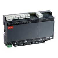
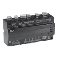
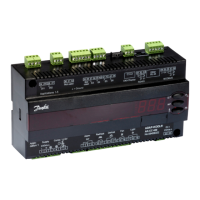
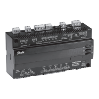
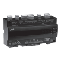
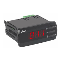
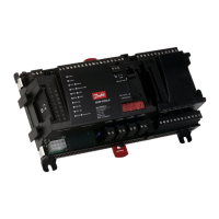
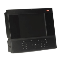
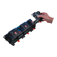
Connections
AI1
Pressure transmitter
AKS 32R
Connect to terminal 40, 41 and 42.
(Use cable 060G1034: Black=40, Brown=41, Blue=42)
The signal from one pressure transmitter can be received by up to 10 controllers. But only if there are no signicant
pressure drops between the evaporators to be controlled. See Figure 39: AKS 32R info.
NOTE:
When replacing AK-CC 550 with AK-CC55, S and ground must be switched.
AI2 - AI7
Primarily for temperature inputs
• S2
Pt 1000 ohm sensor AKS11, placed at the evaporator outlet
• S3, S4, S5
Pt 1000 AKS11, PTC 1000 EKS111, NTC5K EKS211 or NTC10K EKS221 sensor. All have to be of the same type.
• S3, return air sensor, placed in the warm air before the evaporator
• S4, discharge air sensor, placed in the cold air after the evaporator
(the need for either S3 or S4 can be selected in the conguration)
• S5, defrost sensor, placed in the evaporator
• S6, Pt 1000 ohm sensor, food temperature sensor placed in-between the food products
(If the DI1 input is used for a temperature measurement e.g. S5B, it will appear as AI7.)
DI1
Digital input signal.
The dened function is active when the input is short-circuited or opened, depending on the function dened in
o02.
DI2
Digital input signal.
The dened function is active when the input is short-circuited or opened, depending on the function dened in
o37.
AO1
Analogue output signal
• Analogue 0 – 10 V
Can be used to drive an external stepper driver.
• Pulse width modulated signal
Can be used for fast pulse control of rail heat via an external power solid state relay.
MODBUS
For data communication.
• Terminal 83 = B-
• Terminal 84 = A+
• Terminal 85 = screen
NOTE:
When replacing AK-CC 550 with AK-CC55 A+, B- and shield must be switched.
Supply voltage
• 230 V AC or 115 V AC
DO1
• AKV valve
Connection of expansion valve type AKV, AKVA, AKVH or AKVP. The coil must be a 230 V or 115 V AC coil.
• Liquid line solenoid valve
© Danfoss | Climate Solutions | 2021.02 BC364229688105en-000101 | 31
AK-CC55 Single Coil and Single Coil UI
 Loading...
