4. Full adaptive:
Full Adaptive mode is ideal for applications where defrost is not requested to be performed at a certain time, but
can be performed whenever ice is starting to interrupt the airow. It makes sense to combine this mode with the
defrost interval timer as a safety timer.
Adaptive defrosting requires the following connections:
• Expansion valve type AKV
• Pe evaporator pressure and S2 gas out temperature
• Temperature signal from both S3 and S4. Sensors must be placed in the airow/channel immediately before / after
the evaporator.
• Condensing temperature Tc is distributed via the network from the system manager. If Tc is not received by the
case controller, the adaptive defrost function is using default back-up values.
NOTE:
Adaptive parameters will be reset after a defrost has been initiated or at main switch in stopped or service mode. At
start up with a warm evaporator (measured with S2 sensor), the evaporator is presumed clean. If the evaporator
temperature is measured below 0.1 °C, adaptive defrost will request a defrost start to secure a clean evaporator.
Min. time between defrosts
There is a preset 2 hours minimum time between defrosts. This avoids that planned defrosts in accordance with the
weekly schedule are carried out immediately after an adaptive defrost has been carried out. The time applies from
when an adaptive defrost has been completed to when a planned defrost is again permitted. The adaptive defrost
will not start defrosting with a shorter interval than the 2 hours either.
Melt function
This function will prevent the air ow in the evaporator from being reduced by frost created by uninterrupted
operation for a long time.
The function is activated if the thermostat temperature has remained in the range between -5 °C and +10 °C for a
longer period than the set melting interval. The refrigeration will then be stopped during the set melting period.
The frost will be melted so that the air ow and hence the evaporator’s capacity will be greatly improved.
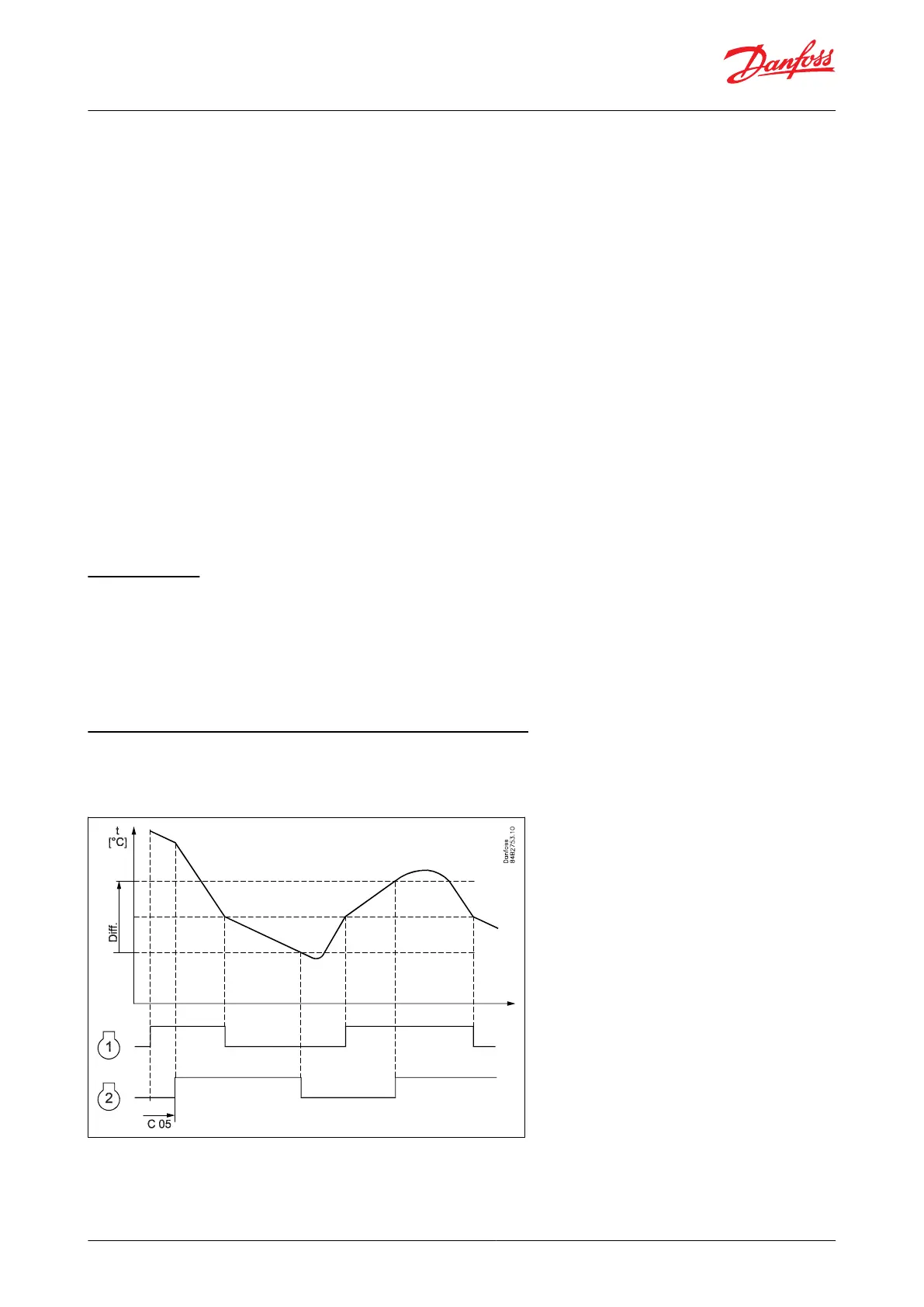
Control of two compressors (only with custom set-up)
Two compressor steps can be controlled cyclic or sequentially. At cyclic control, two compressors must be of the
same size, while in sequential control compressor step 1 can be larger than step 2.
Figure 12: Control of two compressors
Cyclic control
When the controller demands refrigeration, it will rst cut in the compressor with the shortest operating time. After
the time delay, the second compressor will be cut in.
© Danfoss | Climate Solutions | 2021.02 BC364229688105en-000101 | 15
AK-CC55 Single Coil and Single Coil UI

 Loading...


