7 RS-485 Installation and Set-up
RS-485 is a two-wire bus interface compatible with multi-
drop network topology, i.e. nodes can be connected as a
bus, or via drop cables from a common trunk line. A total
of 32 nodes can be connected to one network segment.
Repeaters divide network segments.
NOTE
Each repeater functions as a node within the segment in
which it is installed. Each node connected within a given
network must have a unique node address, across all
segments.
Terminate each segment at both ends, using either the
termination switch (S801) of the frequency converters or a
biased termination resistor network. Always use screened
twisted pair (STP) cable for bus cabling, and always follow
good common installation practice.
Low-impedance earth connection of the screen at every
node is important, including at high frequencies. Thus,
connect a large surface of the screen to earth, for example
with a cable clamp or a conductive cable gland. It may be
necessary to apply potential-equalizing cables to maintain
the same earth potential throughout the network - partic-
ularly in installations with long cables.
To prevent impedance mismatch, always use the same
type of cable throughout the entire network. When
connecting a motor to the frequency converters, always
use screened motor cable.
Cable:
Screened twisted pair (STP)
Impedance:
120 Ω
Cable length:
Max. 1200 m (including drop lines)
Max. 500 m station-to-station
Table 7.1
7.1.1
Network Connection
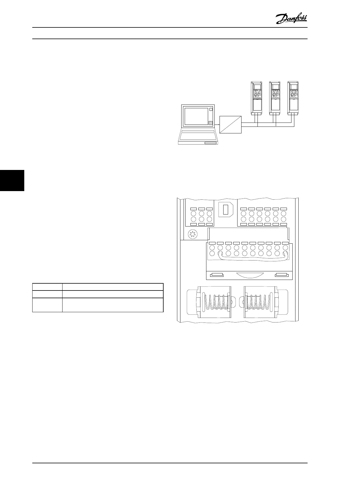
One or more frequency converters can be connected to a
control (or master) using the RS-485 standardised interface.
Terminal 68 is connected to the P signal (TX+, RX+), while
terminal 69 is connected to the N signal (TX-,RX-).
If more than one frequency converter is connected to a
master, use parallel connections.
130BA060.11
68 69 68 69 68 69
RS 485
RS 232
USB
+
-
Illustration 7.1
In order to avoid potential equalizing currents in the
screen, earth the cable screen via terminal 61, which is
connected to the frame via an RC link.
130BB021.10
12 13 18 19 27 29 32
33 20 37
Remove jumper to enable Safe Stop
61 68 69 39 42 50 53 54 55
Illustration 7.2 Control Card Terminals
The RS-485 bus must be terminated by a resistor network
at both ends. For this purpose, set switch S801 on the
control card for "ON".
For more information, see 4.8.2 Switches S201, S202, and
S801 .
Communication protocol must be set to 8-30 Protocol.
RS-485 Installation and Set... VLT Automation Low Harmonic Drive Operating Instructions
132 MG34O202 - VLT
®
is a registered Danfoss trademark
77
 Loading...


