6.3 Parameter Lists - Frequency Converter
Changes during operation
”TRUE” means that the parameter can be changed while
the frequency converter is in operation and “FALSE” means
that the it must be stopped before a change can be made.
4-Set-up
'All set-up': the parameters can be set individually in each
of the four set-ups, i.e. one single parameter can have four
different data values.
’1 set-up’: data value will be the same in all set-ups.
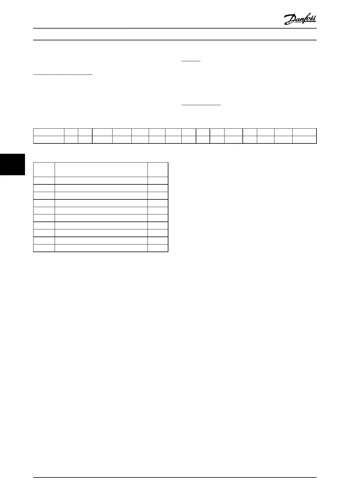
Conversion index
This number refers to a conversion figure used when
writing or reading to and from the frequency converter.
Conv. index 100 67 6 5 4 3 2 1 0 -1 -2 -3 -4 -5 -6
Conv. factor 1 1/60 1000000 100000 10000 1000 100 10 1 0.1 0.01 0.001 0.0001 0.00001 0.000001
Table 6.13
Data
type
Description Type
2 Integer 8 Int8
3 Integer 16 Int16
4 Integer 32 Int32
5 Unsigned 8 Uint8
6 Unsigned 16 Uint16
7 Unsigned 32 Uint32
9 Visible String VisStr
33 Normalized value 2 bytes N2
35 Bit sequence of 16 boolean variables V2
54 Time difference w/o date TimD
Table 6.14
See the frequency converter Design Guide for further
information about data types 33, 35 and 54.
Parameters for the frequency converter are grouped into
various parameter groups for easy selection of the correct
parameters for optimized operation of the frequency
converter.
0-** Operation and Display parameters for basic frequency
converter settings
1-** Load and Motor parameters, includes all load and
motor related parameters
2-** Brake parameters
3-** References and ramping parameters, includes DigiPot
function
4-** Limits Warnings, setting of limits and warning
parameters
5-** Digital inputs and outputs, includes relay controls
6-** Analog inputs and outputs
7-** Controls, setting parameters for speed and process
controls
8-** Communication and option parameters, setting of FC
RS485 and FC USB port parameters.
9-** Profibus parameters
10-** DeviceNet and CAN Fieldbus parameters
12-** Ethernet parameters
13-** Smart Logic Control parameters
14-** Special function parameters
15-** Drive information parameters
16-** Read out parameters
17-** Encoder Option parameters
18-** Data Readouts 2
30-** Special Features
32-** MCO 305 Basic parameters
33-** MCO 305 Advanced parameters
34-** MCO Data Readout parameters
35-** Sensor Input Option
How to Programme the Low Ha... VLT Automation Low Harmonic Drive Operating Instructions
90 MG34O202 - VLT
®
is a registered Danfoss trademark
6
6
 Loading...


