7.1.2 EMC Precautions
The following EMC precautions are recommended in order
to achieve interference-free operation of the RS-485
network.
Relevant national and local regulations, for example
regarding protective earth connection, must be observed.
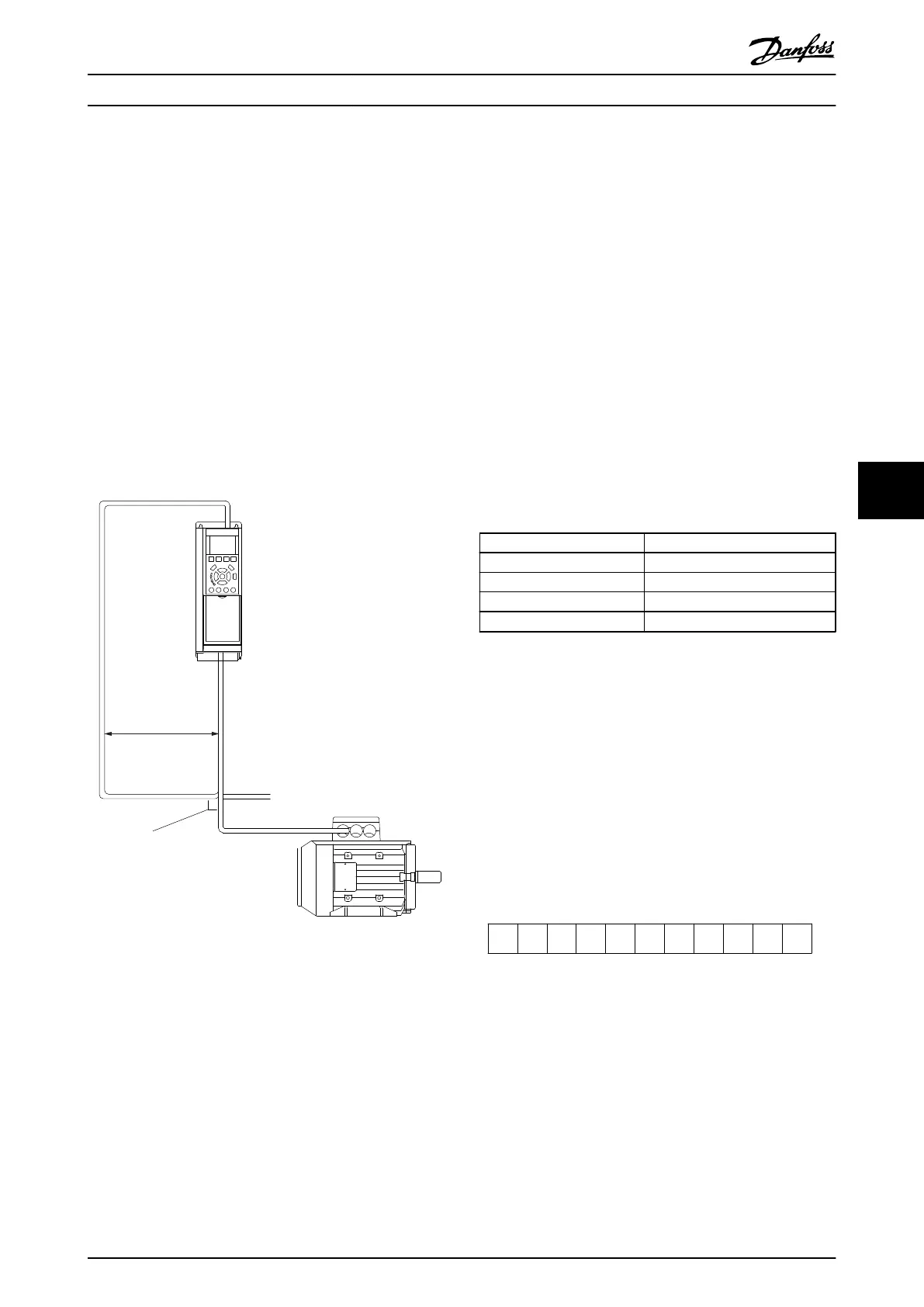
The RS-485 communication cable must be kept away from
motor and brake resistor cables to avoid coupling of high
frequency noise from one cable to another. Normally a
distance of 200 mm (8 inches) is sufficient, but keeping the
greatest possible distance between the cables is generally
recommended, especially where cables run in parallel over
long distances. When crossing is unavoidable, the RS-485
cable must cross motor and brake resistor cables at an
angle of 90 degrees.
Fieldbus cable
Min.200mm
90° crossing
130BA080.11
Illustration 7.3
The FC protocol, also referred to as FC bus or Standard
bus, is the Danfoss standard fieldbus. It defines an access
technique according to the master-slave principle for
communications via a serial bus.
One master and a maximum of 126 slaves can be
connected to the bus. The master selects the individual
slaves via an address character in the telegram. A slave
itself can never transmit without first being requested to
do so, and direct message transfer between the individual
slaves is not possible. Communications occur in the half-
duplex mode.
The master function cannot be transferred to another node
(single-master system).
The physical layer is RS-485, thus utilizing the RS-485 port
built into the frequency converter. The FC protocol
supports different telegram formats:
•
A short format of 8 bytes for process data.
•
A long format of 16 bytes that also includes a
parameter channel.
•
A format used for texts.
7.2 Network Configuration
7.2.1 Set-up
Set the following parameters to enable the FC protocol for
the frequency converter.
Parameter Number Setting
8-30 Protocol
FC
8-31 Address
1 - 126
8-32 FC Port Baud Rate
2400 - 115200
8-33 Parity / Stop Bits
Even parity, 1 stop bit (default)
Table 7.2
7.3
FC Protocol Message Framing Structure
7.3.1 Content of a Character (byte)
Each character transferred begins with a start bit. Then 8
data bits are transferred, corresponding to a byte. Each
character is secured via a parity bit. This bit is set at "1"
when it reaches parity. Parity is when there is an equal
number of 1s in the 8 data bits and the parity bit in total.
A stop bit completes a character, thus consisting of 11 bits
in all.
0 1 32 4 5 6 7
195NA036.10
Start
bit
Even Stop
Parity bit
Illustration 7.4
7.3.2 Telegram Structure
Each telegram has the following structure:
1. Start character (STX)=02 Hex
2. A byte denoting the telegram length (LGE)
3. A byte denoting the frequency converter address
(ADR)
RS-485 Installation and Set... VLT Automation Low Harmonic Drive Operating Instructions
MG34O202 - VLT
®
is a registered Danfoss trademark 133
7 7
 Loading...


