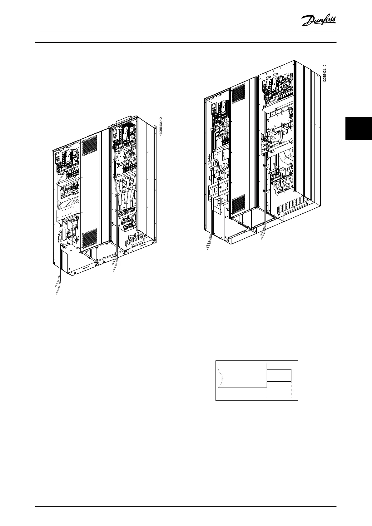
Fieldbus connection
Connections are made to the relevant options on the
control card. For details, see the relevant fieldbus
instruction. The cable must be placed in the provided path
inside the frequency converter and tied down together
with other control wires (see Illustration 4.32 and
Illustration 4.33).
Illustration 4.32 Control card wiring path for the D13
Illustration 4.33 Control card wiring path for the E9
4.6.21
Access to Control Terminals
All terminals to the control cables are located beneath the
LCP (both filter and frequency converter LCP). They are
accessed by opening the door of the unit.
4.6.22
Electrical Installation, Control
Terminals
To connect the cable to the terminal:
1. Strip insulation by about 9-10 mm
130BA150.10
9 - 10 mm
(0.37 in)
2.
Insert a screwdriver
1)
in the square hole.
How to Install VLT Automation Low Harmonic Drive Operating Instructions
MG34O202 - VLT
®
is a registered Danfoss trademark 51
4 4
 Loading...


