5 How to Operate the Low Harmonic Drive
5.1.1 Ways of Operation
The Low Harmonic Drive can be operated in 2 ways:
1. Graphical Local Control Panel (GLCP)
2. RS-485 serial communication or USB, both for PC
connection
5.1.2 How to Operate Graphical LCP (GLCP)
The Low Harmonic Drive is equipped with two LCPs, one
on the frequency converter section (to the right) of the
drive and one on the active filter section (to the left). The
filter LCP is operated the same way as the frequency
converter LCP. Each LCP controls only the unit it is
connected to and there is no communication between the
two LCPs.
NOTE
The active filter should be in Auto Mode, i.e. the [Auto On]
key must be pressed on the filter LCP.
The following instructions are valid for the GLCP (LCP 102).
The GLCP is divided into four functional groups:
1. Graphical display with Status lines.
2. Menu keys and indicator lights (LEDs) - selecting
mode, changing parameters and switching
between display functions.
3. Navigation keys and indicator lights (LEDs).
4. Operation keys and indicator lights (LEDs).
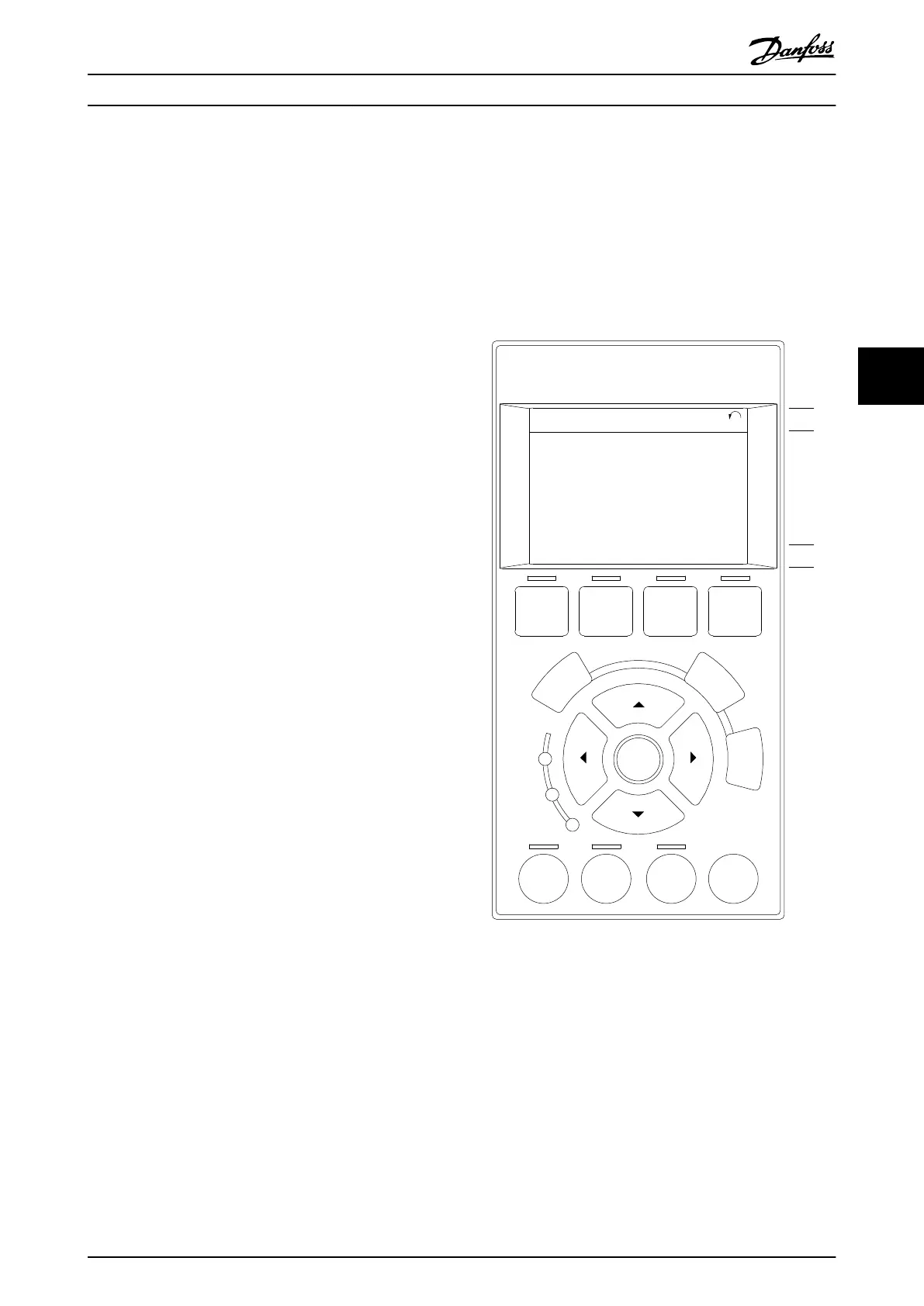
Graphical display:
The LCD-display is back-lit with a total of 6 alpha-numeric
lines. All data is displayed on the LCP which can show up
to five operating variables while in [Status] mode.
Illustration 5.1 shows an example of the frequency
converter LCP. The filter LCP looks identical but displays
information related to the filter operation.
Display lines:
a. Status line: Status messages displaying icons and
graphics.
b. Line 1-2: Operator data lines displaying data and
variables defined or chosen by the user. By
pressing the [Status] key, up to one extra line can
be added.
c. Status line: Status messages displaying text.
The display is divided into 3 sections:
Top section (a)
shows the status when in status mode or up to 2 variables
when not in status mode and in the case of Alarm/
Warning.
Auto
on
Reset
Hand
on
O
Status
Quick
Menu
Main
Menu
Alarm
Log
Back
Cancel
Info
OK
Status
1(0)
1234rpm 10,4A 43,5Hz
Run OK
43,5Hz
On
Alarm
Warn.
130BA018.13
1
2
3
4
b
a
c
Illustration 5.1 LCP
The number of the Active Set-up (selected as the Active
Set-up in 0-10 Active Set-up) is shown. When programming
in another Set-up than the Active Set-up, the number of
the Set-up being programmed appears to the right in
brackets.
Middle section (b)
shows up to 5 variables with related unit, regardless of
status. In case of alarm/warning, the warning is shown
instead of the variables.
How to Operate the Low Harm... VLT Automation Low Harmonic Drive Operating Instructions
MG34O202 - VLT
®
is a registered Danfoss trademark 59
5 5
 Loading...


