1-04 Overload Mode
Option: Function:
[0] * High torque Allows up to 160% over torque.
[1] Normal torque For oversized motor - allows up to 110%
over torque.
NOTE
This parameter cannot be adjusted while the motor is
running.
1-90 Motor Thermal Protection
Option: Function:
Thermal motor protection can be
implemented using a range of techniques:
•
Via a PTC sensor in the motor
windings connected to one of the
analog or digital inputs
(1-93 Thermistor Source). See
6.1.3.1 PTC Thermistor Connection.
•
Via a KTY sensor in the motor
winding connected to an analog
input (1-96 KTY Thermistor Resource).
See 6.1.3.2 KTY Sensor Connection.
•
Via calculation (ETR = Electronic
Thermal Relay) of the thermal load,
based on the actual load and time.
The calculated thermal load is
compared with the rated motor
current I
M,N
and the rated motor
frequency f
M,N
. See 6.1.3.3 ETR and .
•
Via a mechanical thermal switch
(Klixon type). See 6.1.3.4 ATEX ETR.
For the North American market: The ETR
functions provide class 20 motor overload
protection in accordance with NEC.
[0]
* No
protection
Continuously overloaded motor, when no
warning or trip of the frequency converter is
required.
[1] Thermistor
warning
Activates a warning when the connected
thermistor or KTY-sensor in the motor reacts
in the event of motor over-temperature.
[2] Thermistor
trip
Stops (trips) frequency converter when
connected thermistor or KTY sensor in the
motor reacts in the event of motor over-
temperature.
The thermistor cut-out value must be > 3
kΩ.
Integrate a thermistor (PTC sensor) in the
motor for winding protection.
[3] ETR warning
1
Calculates the load when set-up 1 is active
and activates a warning on the display when
1-90 Motor Thermal Protection
Option: Function:
the motor is overloaded. Programme a
warning signal via one of the digital outputs.
[4] ETR trip 1 Calculates the load when set-up 1 is active
and stops (trips) frequency converter when
the motor is overloaded. Programme a
warning signal via one of the digital outputs.
The signal appears in the event of a warning
and if the frequency converter trips (thermal
warning).
[5] ETR warning
2
[6] ETR trip 2
[7] ETR warning
3
[8] ETR trip 3
[9] ETR warning
4
[10] ETR trip 4
NOTE
If [20] is selected, follow strictly the instructions described
in the dedicated chapter of the VLT AutomationDrive
design guide and the instructions given by the motor
manufacturer.
NOTE
If [20] is selected, 4-18 Current Limit must be set to 150%.
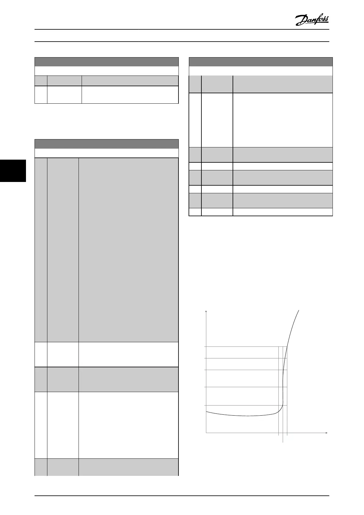
6.1.3.1 PTC Thermistor Connection
1330
550
250
-20°C
175HA183.10
4000
3000
R
(Ω)
nominel
nominel -5°C
nominel +5°C
[°C]
Illustration 6.2 PTC profile
Using a digital input and 10 V as power supply:
How to Programme the Low Ha... VLT Automation Low Harmonic Drive Operating Instructions
70 MG34O202 - VLT
®
is a registered Danfoss trademark
6
6
 Loading...


