NOTE
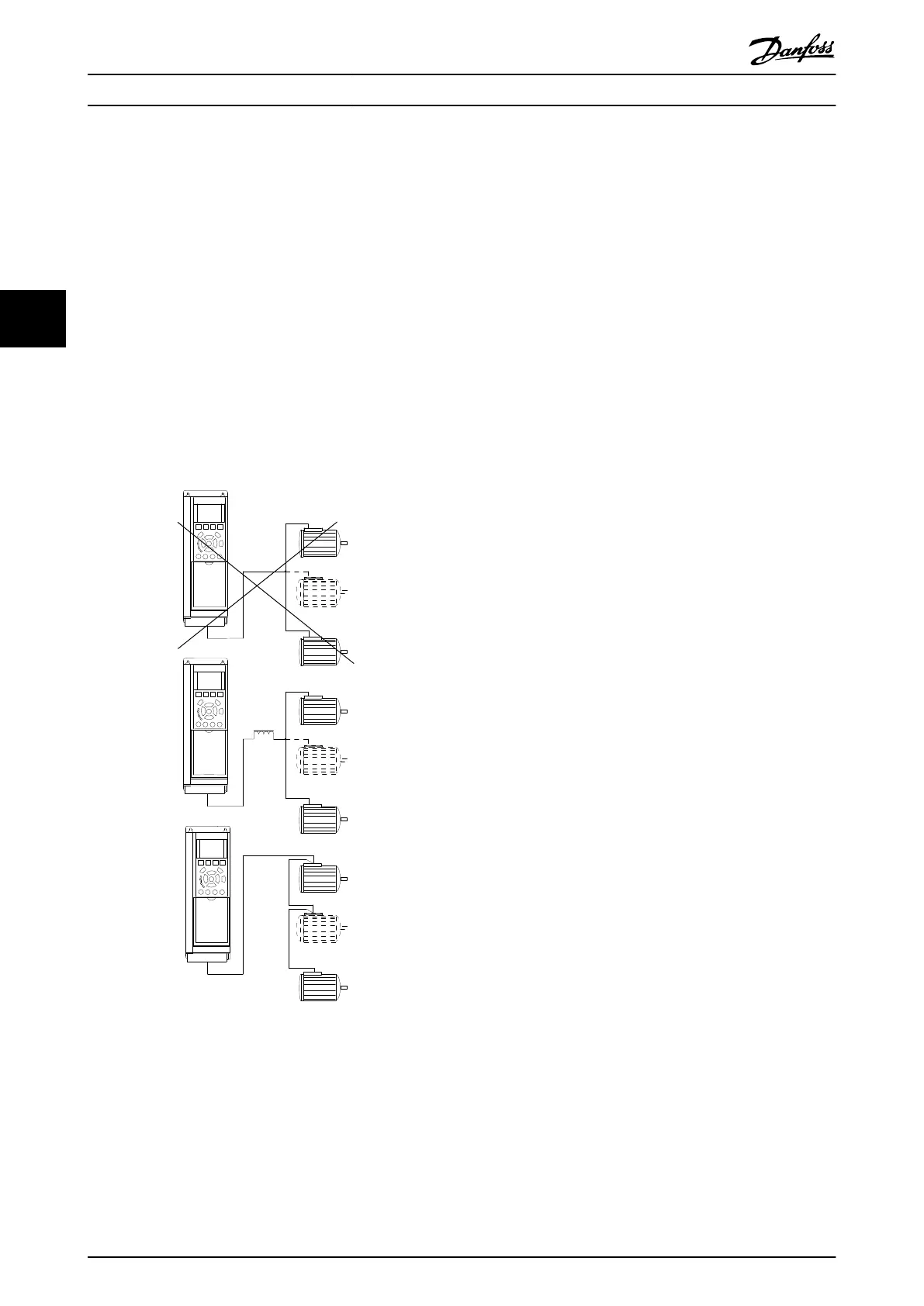
Installations with cables connected in a common joint as in
Illustration 4.45, is only recommended for short cable
lengths.
NOTE
When motors are connected in parallel, 1-29 Automatic
Motor Adaptation (AMA) cannot be used.
NOTE
The electronic thermal relay (ETR) of the frequency
converter cannot be used as motor protection for the
individual motor in systems with parallel-connected
motors. Provide further motor protection by e.g.
thermistors in each motor or individual thermal relays
(circuit breakers are not suitable as protection).
Illustration 4.45 Installations with cables connected in a common
joint
Problems may arise at start and at low RPM values if motor
sizes are widely different because small motors' relatively
high ohmic resistance in the stator calls for a higher
voltage at start and at low RPM values.
4.10.3
Motor Thermal Protection
The electronic thermal relay in the frequency converter has
received UL-approval for single motor protection, when
1-90 Motor Thermal Protectionis set for ETR Trip and
1-24 Motor Current is set to the rated motor current (see
motor name plate).
For thermal motor protection it is also possible to use the
MCB 112 PTC Thermistor Card option. This card provides
ATEX certificate to protect motors in explosion hazardous
areas, Zone 1/21 and Zone 2/22. When 1-90 Motor Thermal
Protection is set to [20] ATEX ETR is combined with the use
of MCB 112, it is possible to control an Ex-e motor in
explosion hazardous areas. Consult the programming
guide for details on how to set up the frequency converter
for safe operation of Ex-e motors.
How to Install VLT Automation Low Harmonic Drive Operating Instructions
58 MG34O202 - VLT
®
is a registered Danfoss trademark
44
 Loading...


