6. Reconnect power and the frequency converter is
reset.
NOTE
First start-up takes a few more seconds.
7. Press [Reset]
14-22 Operation Mode initialises all except:
14-50 RFI Filter
8-30 Protocol
8-31 Address
8-32 Baud Rate
8-35 Minimum Response Delay
8-36 Max Response Delay
8-37 Maximum Inter-Char Delay
15-00 Operating Hours to 15-05 Over Volt's
15-20 Historic Log: Event to 15-22 Historic Log: Time
15-30 Alarm Log: Error Code to 15-32 Alarm Log: Time
NOTE
Parameters selected in 0-25 My Personal Menu, will stay
present, with default factory setting.
Manual initialisation
NOTE
When carrying out manual initialisation, serial communi-
cation, RFI filter settings and fault log settings are reset.
Removes parameters selected in 0-25 My Personal Menu.
1. Disconnect from mains and wait until the
display turns off.
2a. Press [Status] - [Main Menu] - [OK] at the
same time while power up for Graphical LCP
(GLCP)
2b. Press [Menu] while power up for LCP 101,
Numerical Display
3. Release the keys after 5 sec.
4. The frequency converter is now programmed
according to default settings
This parameter initialises all except:
15-00 Operating Hours
15-03 Power Up's
15-04 Over Temp's
15-05 Over Volt's
5.1.10
RS-485 Bus Connection
Both filter portion and frequency converter can be
connected to a controller (or master) together with other
loads using the RS-485 standard interface. Terminal 68 is
connected to the P signal (TX+, RX+), while terminal 69 is
connected to the N signal (TX-,RX-).
Always use parallel connections for the Low Harmonic
Drive to ensure that both filter and drive part is connected.
130BA060.11
68 69 68 69 68 69
RS 485
RS 232
USB
+
-
Illustration 5.16 Connection Example
To avoid potential equalizing currents in the screen, earth
the cable screen via terminal 61, which is connected to the
frame via an RC-link.
Bus termination
The RS-485 bus must be terminated by a resistor network
at both ends. If the frequency converter is the first or the
last device in the RS-485 loop, set the switch S801 on the
control card for ON.
For more information, see the paragraph Switches S201,
S202, and S801.
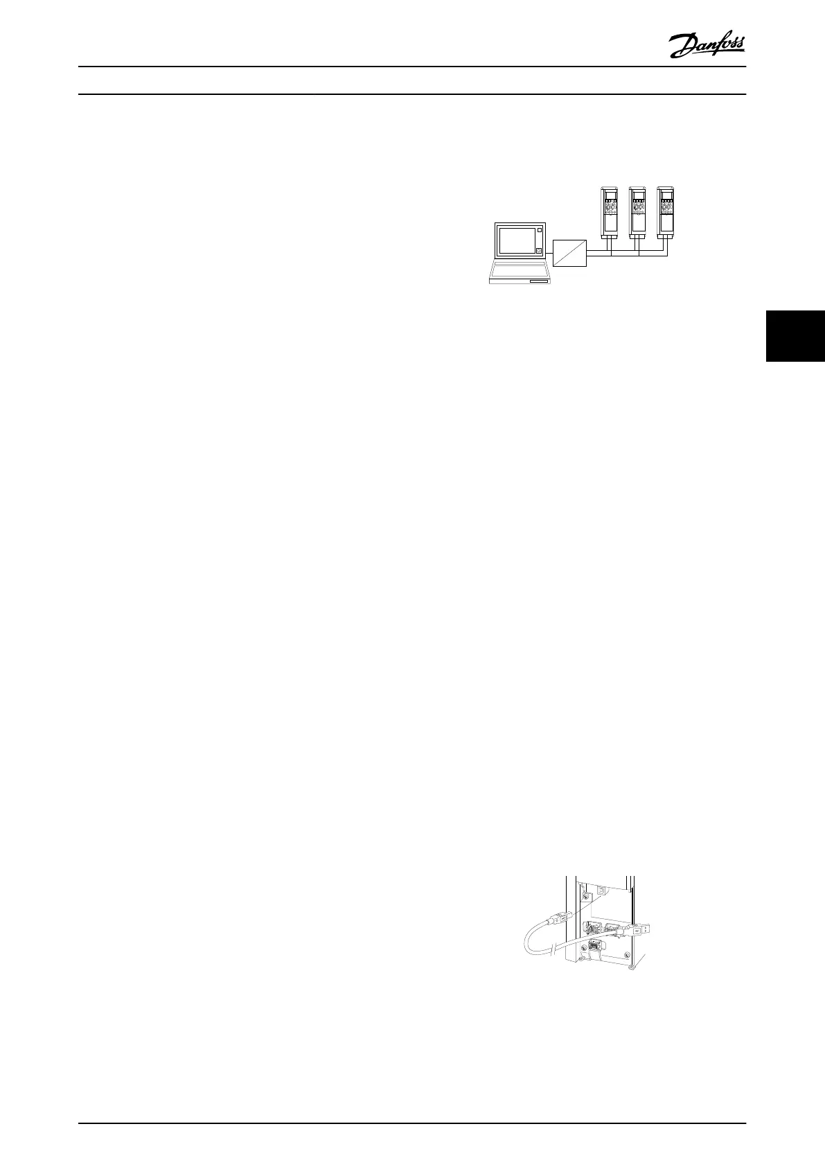
5.1.11
How to Connect a PC to the
Frequency Converter
To control or program the frequency converter (and the
filter part) from a PC, install the PC-based Configuration
Tool MCT 10.
The PC is connected via a standard (host/device) USB cable
to both devices, or via the RS-485 interface as shown in
the VLT HVAC Drive Design Guide, MG11BXYY, chapter How
to Install > Installation of misc. connections.
NOTE
The USB connection is galvanically isolated from the
supply voltage (PELV) and other high-voltage terminals.
The USB connection is connected to protection earth on
the frequency converter. Use only an isolated laptop as PC
connection to the USB connector on the frequency
converter.
Illustration 5.17 For control cable connections, see 4.8.1
Electrical Installation, Control Cables .
How to Operate the Low Harm... VLT Automation Low Harmonic Drive Operating Instructions
MG34O202 - VLT
®
is a registered Danfoss trademark 65
5 5
 Loading...


