Parameter Description of function
7-00 Speed PID Feedback Source Select from which input the Speed PID should get its feedback.
7-02 Speed PID Proportional Gain The higher the value - the quicker the control. However, too high value may lead to oscillations.
7-03 Speed PID Integral Time
Eliminates steady state speed error. Lower value means quick reaction. However, too low value may
lead to oscillations.
7-04 Speed PID Differentiation
Time
Provides a gain proportional to the rate of change of the feedback. A setting of zero disables the
differentiator.
7-05 Speed PID Diff. Gain Limit
If there are quick changes in reference or feedback in a given application - which means that the error
changes swiftly - the differentiator may soon become too dominant. This is because it reacts to
changes in the error. The quicker the error changes, the stronger the differentiator gain is. The differ-
entiator gain can thus be limited to allow setting of the reasonable differentiation time for slow
changes and a suitably quick gain for quick changes.
7-06 Speed PID Lowpass Filter
Time
A low-pass filter that dampens oscillations on the feedback signal and improves steady state
performance. However, too large filter time deteriorates the dynamic performance of the Speed PID
control.
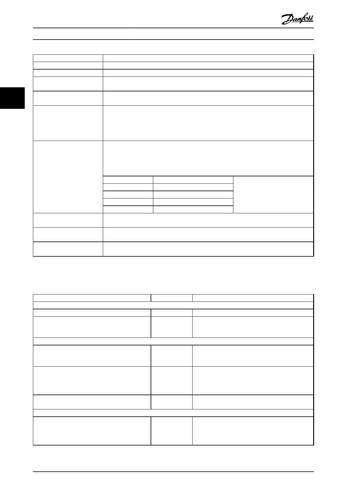
Practical settings of parameter 7-06 taken from the number of pulses per revolution on from encoder
(PPR):
Encoder PPR 7-06 Speed PID Lowpass Filter Time
512 10 ms
1024 5 ms
2048 2 ms
4096 1 ms
7-07 Speed PID Feedback Gear
Ratio
The frequency converter multiplies the speed feedback by this ratio.
7-08 Speed PID Feed Forward
Factor
The reference signal bypasses the speed controller by the amount specified. This feature increases the
dynamic performance of the speed control loop.
7-09 Speed PID Error Correction
w/ Ramp
The speed error between ramp and actual speed is held up against the setting in this parameter. If the
speed error exceeds this parameter entry, the speed error is corrected via ramping in a controlled way.
Table 3.2 Relevant Parameters for Speed Control
Programme in the order shown (see explanation of settings in the Programming Guide)
In Table 3.3 it is assumed that all other parameters and switches remain at their default setting.
Function Parameter Setting
1) Make sure the motor runs properly. Do the following:
Set the motor parameters using name plate data 1-2* As specified by motor name plate
Perform an Automatic Motor Adaptation 1-29 Automatic
Motor Adaptation
(AMA)
[1] Enable complete AMA
2) Check the motor is running and the encoder is attached properly. Do the following:
Press [Hand On] on the LCP. Check that the motor is
running and note in which direction it is turning
(henceforth referred to as the “positive direction”).
Set a positive reference.
Go to 16-20 Motor Angle. Turn the motor slowly in the
positive direction. It must be turned so slowly (only a
few RPM) that it can be determined if the value in
16-20 Motor Angle is increasing or decreasing.
16-20 Motor Angle N.A. (read-only parameter) Note: An increasing value
overflows at 65535 and starts again at 0.
If 16-20 Motor Angle is decreasing, change the encoder
direction in 5-71 Term 32/33 Encoder Direction.
5-71 Term 32/33
Encoder Direction
[1] Counter clockwise (if 16-20 Motor Angle is decreasing)
3) Make sure the frequency converter limits are set to safe values
Set acceptable limits for the references. 3-02 Minimum
Reference
3-03 Maximum
Reference
0 RPM (default)
1500 RPM (default)
Basic Operating Principles
VLT
®
AutomationDrive FC 301/FC 302 Design Guide, 0.25-75 kW
24 MG33BF02 - Rev. 2013-12-20
33
 Loading...


