Back
Cancel
Info
OK
On
Alarm
Warn.
2
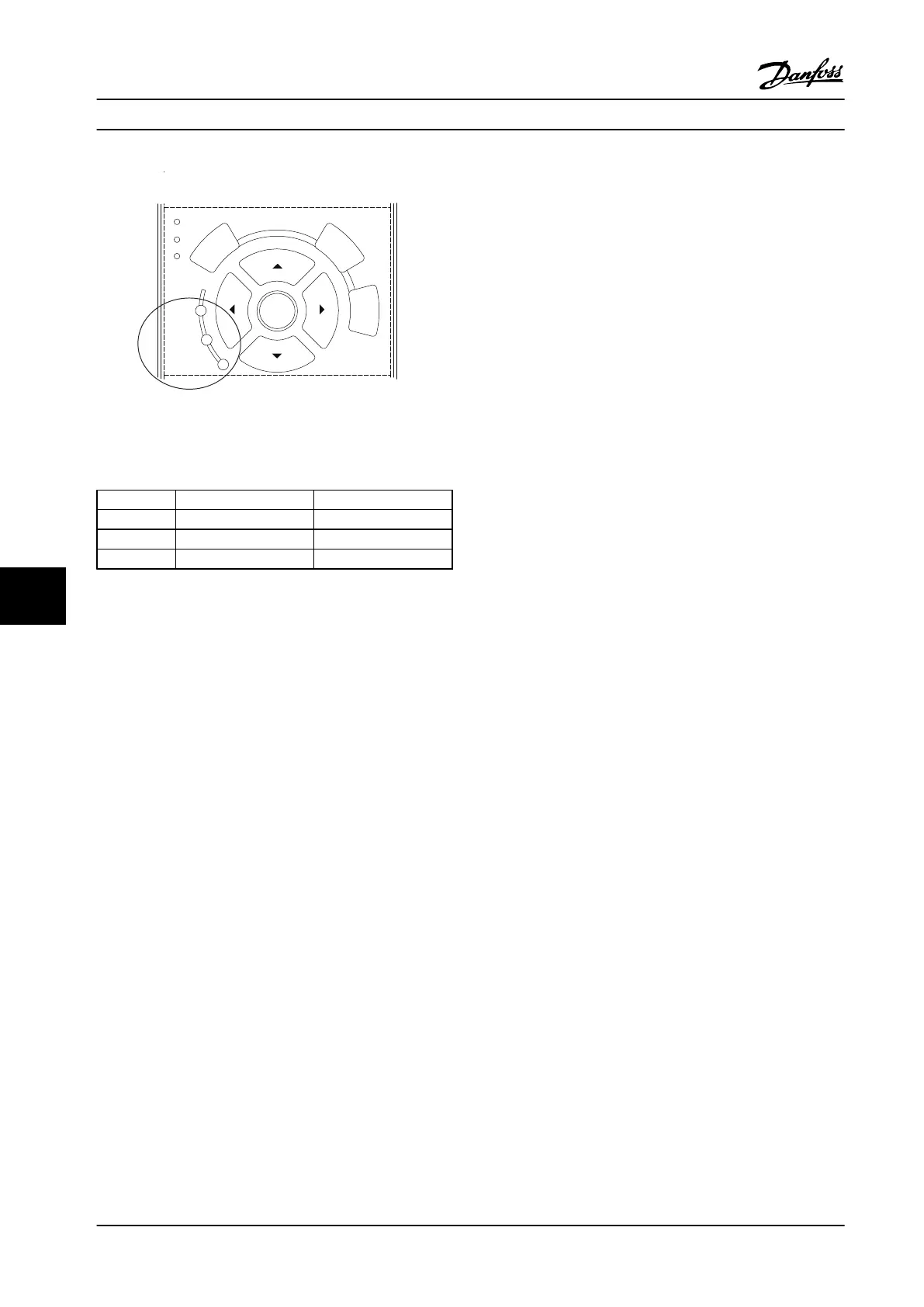
130BB467.11
Figure 9.3 Status Indicator Lights
Warning LED Alarm LED
Warning On Off
Alarm Off On (Flashing)
Trip Lock On On (Flashing)
Table 9.1 Status Indicator Lights Explanations
9.4
Warnings and Alarm Definitions -
Adjustable Frequency Drive
The warning/alarm information below defines each
warning/alarm condition, provides the probable cause for
the condition, and details a remedy or troubleshooting
procedure.
WARNING 1, 10 Volts low
The control card voltage is below 10 V from terminal 50.
Remove some of the load from terminal 50, as the 10 V
supply is overloaded. Max. 15 mA or minimum 590 Ω.
A short circuit in a connected potentiometer or improper
wiring of the potentiometer can cause this condition.
Troubleshooting
Remove the wiring from terminal 50. If the
warning clears, the problem is with the wiring. If
the warning does not clear, replace the control
card.
WARNING/ALARM 2, Live zero error
This warning or alarm only appears if programmed in
6-01 Live Zero Timeout Function. The signal on one of the
analog inputs is less than 50% of the minimum value
programmed for that input. Broken wiring or faulty device
sending the signal can cause this condition.
Troubleshooting
Check connections on all the analog input
terminals. Control card terminals 53 and 54 for
signals, terminal 55 common. MCB 101 terminals
11 and 12 for signals, terminal 10 common. MCB
109 terminals 1, 3, 5 for signals, terminals 2, 4, 6
common).
Check that the adjustable frequency drive
programming and switch settings match the
analog signal type.
Perform input terminal signal test.
WARNING/ALARM 3, No motor
No motor has been connected to the output of the
frequency converter.
WARNING/ALARM 4, Mains phase loss
A phase is missing on the supply side, or the line voltage
imbalance is too high. This message also appears for a
fault in the input rectifier on the adjustable frequency
drive. Options are programmed at 14-12 Function at Mains
Imbalance.
Troubleshooting
Check the supply voltage and supply currents to
the adjustable frequency drive.
WARNING 5, DC link voltage high
The intermediate circuit voltage (DC) is higher than the
high-voltage warning limit. The limit is dependent on the
adjustable frequency drive voltage rating. The unit is still
active.
WARNING 6, DC link voltage low
The intermediate circuit voltage (DC) is lower than the low-
voltage warning limit. The limit is dependent on the
frequency converter voltage rating. The unit is still active.
WARNING/ALARM 7, DC overvoltage
If the intermediate circuit voltage exceeds the limit, the
adjustable frequency drive trips after a time.
Troubleshooting
Connect a brake resistor
Extend the ramp time
Change the ramp type
Activate the functions in 2-10 Brake Function
Increase 14-26 Trip Delay at Inverter Fault
If the alarm/warning occurs during a power sag,
use kinetic backup (14-10 Line Failure)
Warnings and Alarms
Instruction Manual
130 Danfoss A/S © Rev. 2014-02-07 All rights reserved. MG37A222
99
 Loading...


