Long control cables and analog signals may result in 50/60
Hz ground loops due to noise from line power supply
cables.
If ground loops occur, break the shield or insert a 100 nF
capacitor between shield and chassis, if needed.
Connect the digital and analog inputs and outputs to the
control cards of the units separately to avoid ground
currents. These connections are on terminals 20, 55, and
39 for both the filter and adjustable frequency drive
sections.
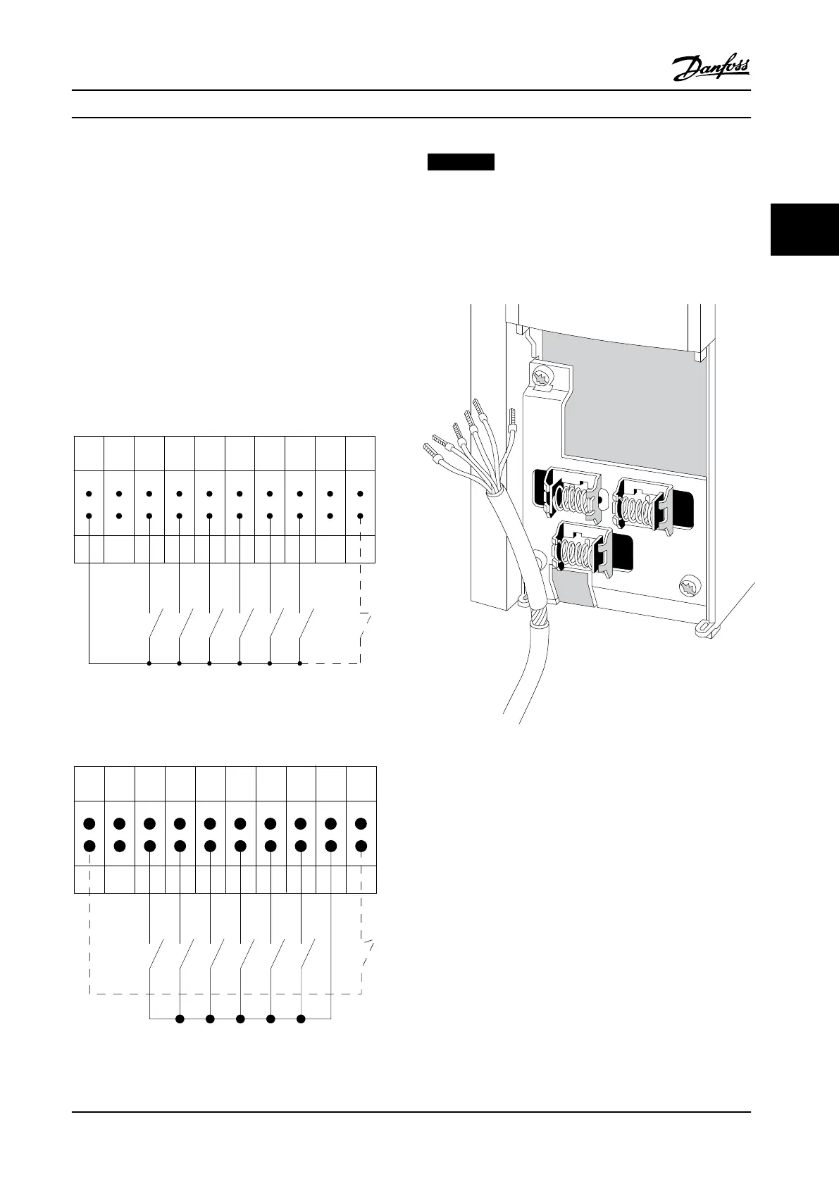
12 13 18 19 27 29 32 33 20 37
+24 V DC
0 VDC
130BT106.10
PNP (Source)
Digital input wiring
Figure 3.27 Input Polarity of Control Terminals, PNP
NPN (Sink)
Digital input wiring
12 13 18 19 27 29 32 33 20 37
+24 V DC
0 VDC
130BT107.11
Figure 3.28 Input Polarity of Control Terminals, NPN
NOTICE!
To comply with EMC emission specifications, shielded/
armored cables are recommended. If using non-shielded/
armored cable, see chapter 3.4.11 Power and Control
Wiring for Non-shielded Cables. If using non-shielded
control cables, use ferrite cores to improve EMC
performance.
Figure 3.29 Connecting Shielded Cables
Connect the shields in a proper way to ensure optimum
electrical immunity.
3.4.21
Safe Torque Off (STO)
To run Safe Torque Off, additional wiring for the adjustable
frequency drive is required, refer to Safe Torque Off
Instruction Manual for Danfoss VLT
®
Adjustable Frequency
Drives for further information.
Installation
Instruction Manual
MG37A222 Danfoss A/S © Rev. 2014-02-07 All rights reserved. 35
3 3
 Loading...


