4) The typical power loss is at nominal load conditions and expected to be within ±15% (tolerance relates to
variances in voltage and cable conditions). Values are based on a typical motor efficiency (IE2/IE3 border line).
Motors with lower efficiency will also add to the power loss in the adjustable frequency drive and vice-versa. If the
switching frequency is increased to the default setting, the power losses may rise significantly. LCP and typical
control card power consumptions are included. Further options and customer load may add up to 30 W to the
losses. (Though typical only 4 W extra for a fully loaded control card, or options for slot A or slot B, each).
Although measurements are made with state-of-the-art equipment, some measurement inaccuracy must be
allowed for (±5%).
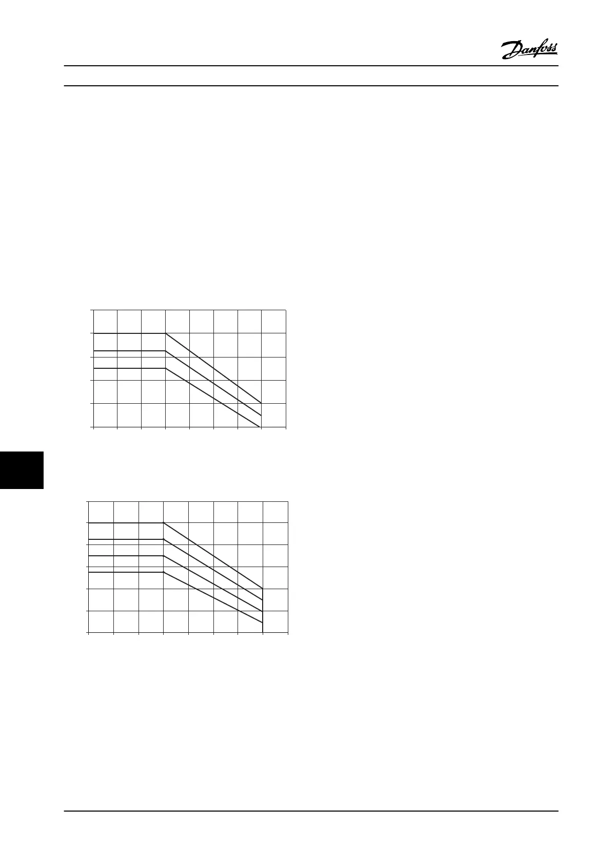
11.1.2 Derating for Temperature
The adjustable frequency drive automatically derates the switching frequency, switching type, or output current under
certain load or ambient conditions as described below. The derating curves in Figure 11.1 and Figure 11.2 apply to both
SFAVM and 60 AVM switching modes.
130BX491.10
Iout [%]
fsw
[kHz]
o
70
80
90
0.5
60
100
110
2.0
50 C
55 C
0.0
o
1.0 1.5 2.5 4.03.0 3.5
o
45 C
Figure 11.1 Derating Frame Sizes D, E, and F 380–500 V (T5) High Overload 150%
130BX492.10
o
70
80
90
0.5
Iout [%]
60
100
110
2.0
fsw
[kHz]
50 C
55 C
0.0
o
1.0 1.5 2.5 4.03.0 3.5
o
45 C
o
40 C
50
Figure 11.2 Derating Frame Sizes D, E, and F 380–500 V (T5) Normal Overload 110%
Specifications Instruction Manual
152 Danfoss A/S © Rev. 2014-02-07 All rights reserved. MG37A222
1111
 Loading...


