A
B
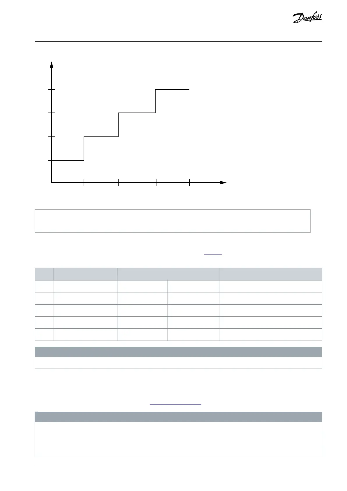
100
75
50
25
0.5 1 1.5 2
e30bh757.10
Illustration 18: Percent of DC Voltage Increments and Reforming Time
5.2 Side-by-side Installation
The drive can be mounted side by side but requires the clearance specified in Table 11 above and below for cooling.
Table 11: Clearance Required for Cooling
Clearance above/below [mm (in)]
N O T I C E
With IP21/NEMA Type1 option kit mounted, a distance of 50 mm (2 in) between the units is required.
5.3 Operating Environment
In environments with airborne liquids, particles, or corrosive gases, ensure that the IP/Type rating of the equipment matches the
installation environment.
For specifications regarding ambient conditions, see 4.5 Ambient Conditions.
N O T I C E
CONDENSATION
Moisture can condense on the electronic components and cause short circuits. Avoid installation in areas subject to frost. Install
an optional space heater when the drive is colder than the ambient air. Operating in standby mode reduces the risk of condensa-
tion as long as the power dissipation keeps the circuitry free of moisture.
AJ330233902305en-000201 / 130R0596 | 37Danfoss A/S © 2021.05
Mechanical Installation
Considerations
VLT® Compressor Drive CDS 803
Design Guide
 Loading...


