2.
•
•
•
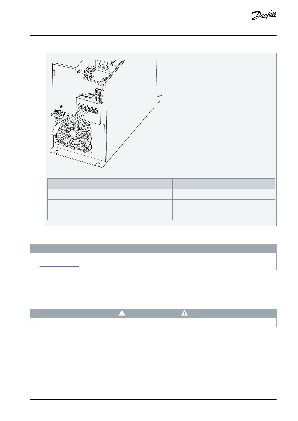
Connect the ground cable to the ground terminal, then connect the compressor to terminals U, V, and W.
Table 16: Connection of Compressor to Terminals
6.3.4.1 IT Grid Installations
N O T I C E
If the drive is supplied from an isolated mains source or mains with grounded leg, the RFI filter is recommended to be disabled,
see 6.5.8 RFI Filter Switch.
Once disabled, the filter capacitors between the chassis and the DC link are cut off to avoid damage to the DC link and to reduce the
ground capacity currents, according to IEC 61800-3. If optimum EMC performance is required, avoid exceeding overvoltage limits
within the DC bus by making sure that the energy charged into the DC link through the RFI filter is either discharged via loading the
DC bus terminals or output terminals U, V, and W.
It is important to use isolation monitors that are rated for use with power electronics (IEC 61557-8).
C A U T I O N
Ensure that the supply voltage does not exceed 440 V (3x380–480 V units) when connected to an IT mains source.
6.3.5 Relay Terminals
Relay 1
Terminal 01: Common.
Terminal 02: Normally open.
Terminal 03: Normally closed.
AJ330233902305en-000201 / 130R0596 | 49Danfoss A/S © 2021.05
Electrical Installation
Considerations
VLT® Compressor Drive CDS 803
Design Guide
 Loading...


