Actual 6.0–22 kW (8.0–30 hp), 380–480 V (typical)
Table 25: Harmonic Current 30 kW (40 hp), 380–480 V
Individual harmonic current I
n
/I
1
(%)
Actual 30 kW (40 hp), IP20, 380–480 V (typical)
Harmonic current distortion factor (%)
Actual 30 kW (40 hp), 380–480 V (typical)
If the short-circuit power of the supply S
sc
is greater than or equal to:
S
SC
= 3 × R
SCE
× U
mains
× I
equ
= 3 × 120 × 400 × I
equ
at the interface point between the user’s supply and the public system (R
sce
).
The installer or user of the equipment is responsible for ensuring that the equipment is connected only to a supply with a short-
circuit power S
sc
greater than or equal to what is specified above. If necessary, consult the distribution network operator. Other
power sizes can be connected to the public supply network by consultation with the distribution network operator.
Compliance with various system level guidelines: The harmonic current data in Table 23 to Table 25 are given in accordance with
IEC/EN 61000-3-12 with reference to the Power Drive Systems product standard. They may be used as the basis for calculation of the
harmonic currents' influence on the power supply system and for the documentation of compliance with relevant regional guide-
lines: IEEE 519 -1992; G5/4.
If there is a need for further reduction of harmonic currents, passive or active filters in front of the drives can be installed. Consult
Danfoss for further information.
6.7 Galvanic Isolation (PELV)
All control terminals and output relay terminals are galvanically isolated from mains power, which completely protects the control-
ler circuitry from the input current. The output relay terminals require their own grounding. This isolation meets the stringent pro-
tective extra-low voltage (PELV) requirements for isolation.
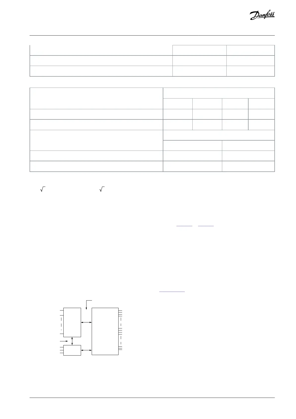
The components that make up the galvanic isolation are illustrated in Illustration 43:
isolation
PELV isolation
Motor
DC-bus
High
voltage
Illustration 43: Galvanic Isolation (PELV)
6.8 Ground Leakage Current
Follow national and local codes regarding protective earthing of equipment where leakage current exceeds 3.5 mA.
Drive technology implies high frequency switching at high power. This generates a leakage current in the ground connection.
AJ330233902305en-000201 / 130R0596 | 63Danfoss A/S © 2021.05
Electrical Installation
Considerations
VLT® Compressor Drive CDS 803
Design Guide
 Loading...


