N O T I C E
Some of the harmonic currents might disturb communication equipment connected to the same transformer or cause resonance
with power factor correction batteries.
To ensure low harmonic currents, the drive is equipped with DC-link coils as standard. This normally reduces the input current I
RMS
by 40%.
The voltage distortion on the mains supply voltage depends on the size of the harmonic currents multiplied by the mains impe-
dance for the frequency in question. The total voltage distortion THDv is calculated based on the individual voltage harmonics us-
ing this formula:
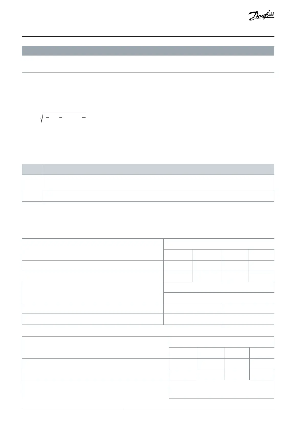
THD % = U
2
5
+ U
2
7
+ ... + U
2
N
(U
N
% of U)
6.6.1 Harmonics Emission Requirements
Equipment is connected to the public supply network.
Table 22: Connected Equipment
IEC/EN 61000-3-2 Class A for 3-phase balanced equipment (for professional equipment only up to 1 kW (1.3 hp) total
power).
IEC/EN 61000-3-12 Equipment 16–75 A and professional equipment as from 1 kW (1.3 hp) up to 16 A phase current.
6.6.2 Harmonics Test Results (Emission)
Power sizes up to 10 kW (15 hp) [200–240 V AC] comply with IEC/EN 61000-3-12, Table 4. Power sizes up to 30 kW (40 hp) [380–
480 V AC] comply with IEC/EN 61000-3-2 Class A and IEC/EN 61000-3-12, Table 4.
Table 23: Harmonic Current 6.0–10 kW (8.0–15 hp), 200 V
Individual harmonic current I
n
/I
1
(%)
Actual 6.0–10 kW (8.0–15 hp), IP20, 200 V (typical)
Harmonic current distortion factor (%)
Actual 6.0–10 kW (8.0–15 hp), 200 V (typical)
Table 24: Harmonic Current 6.0–22 kW (8.0–30 hp), 380–480 V
Individual harmonic current I
n
/I
1
(%)
Actual 6.0–22 kW (8.0–30 hp), IP20, 380–480 V (typical)
Harmonic current distortion factor (%)
AJ330233902305en-000201 / 130R059662 | Danfoss A/S © 2021.05
Electrical Installation
Considerations
VLT® Compressor Drive CDS 803
Design Guide
 Loading...


