•
•
•
•
Programmable logic controller (PLC)
Minimum 16 mm
2
(6 AWG) equalizing cable
Minimum 200 mm (7.9 in) between control cables,
motor cables, and mains cables
Mains supply options, see IEC/EN 61800-5-1
Brake cable (shielded) – not shown, but same
gounding principle applies as for motor cable
Cable insulation stripped
Common ground busbar. Follow local and national
requirements for cabinet grounding.
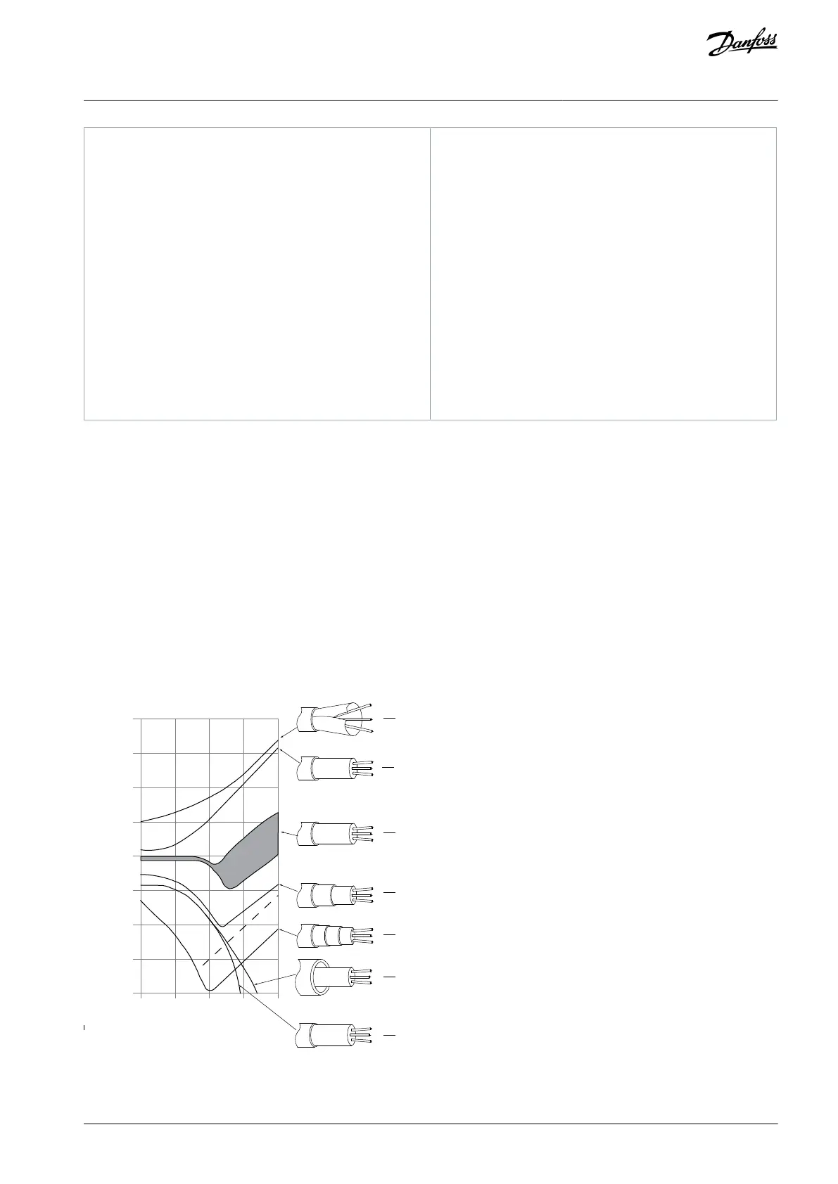
6.5.6 EMC-compliant Cables
To optimize EMC immunity of the control cables and emission from the motor cables, use braided shielded/armored cables.
The ability of a cable to reduce the in- and outgoing radiation of electric noise depends on the transfer impedance (Z
T
). The shield of
a cable is normally designed to reduce the transfer of electric noise. However, a shield with a lower transfer impedance (Z
T
) value is
more effective than a shield with a higher transfer impedance (Z
T
).
Cable manufacturers rarely state the transfer impedance (Z
T
), but it is often possible to estimate transfer impedance (Z
T
) by assess-
ing the physical design of the cable.
Transfer impedance (Z
T
) can be assessed based on the following factors:
The conductibility of the shield material.
The contact resistance between the individual shield conductors.
The shield coverage, that is, the physical area of the cable covered by the shield - often stated as a percentage value.
Shield type (braided or twisted).
e75za166.14
0.01 0.1 1 10 100
10ˉ²
10ˉ³
10ˉ¹
1
10¹
10²
10⁴
10³
10⁵
1
mΩ/m
MHz
2
3
4
5
6
7
Illustration 37: Transfer Impedance (Z
T
)
AJ330233902305en-000201 / 130R0596 | 59Danfoss A/S © 2021.05
Electrical Installation
Considerations
VLT® Compressor Drive CDS 803
Design Guide
 Loading...


