NOTICE!
Note for reassembly: DC capacitor must fit into the
retaining stud at the bottom.
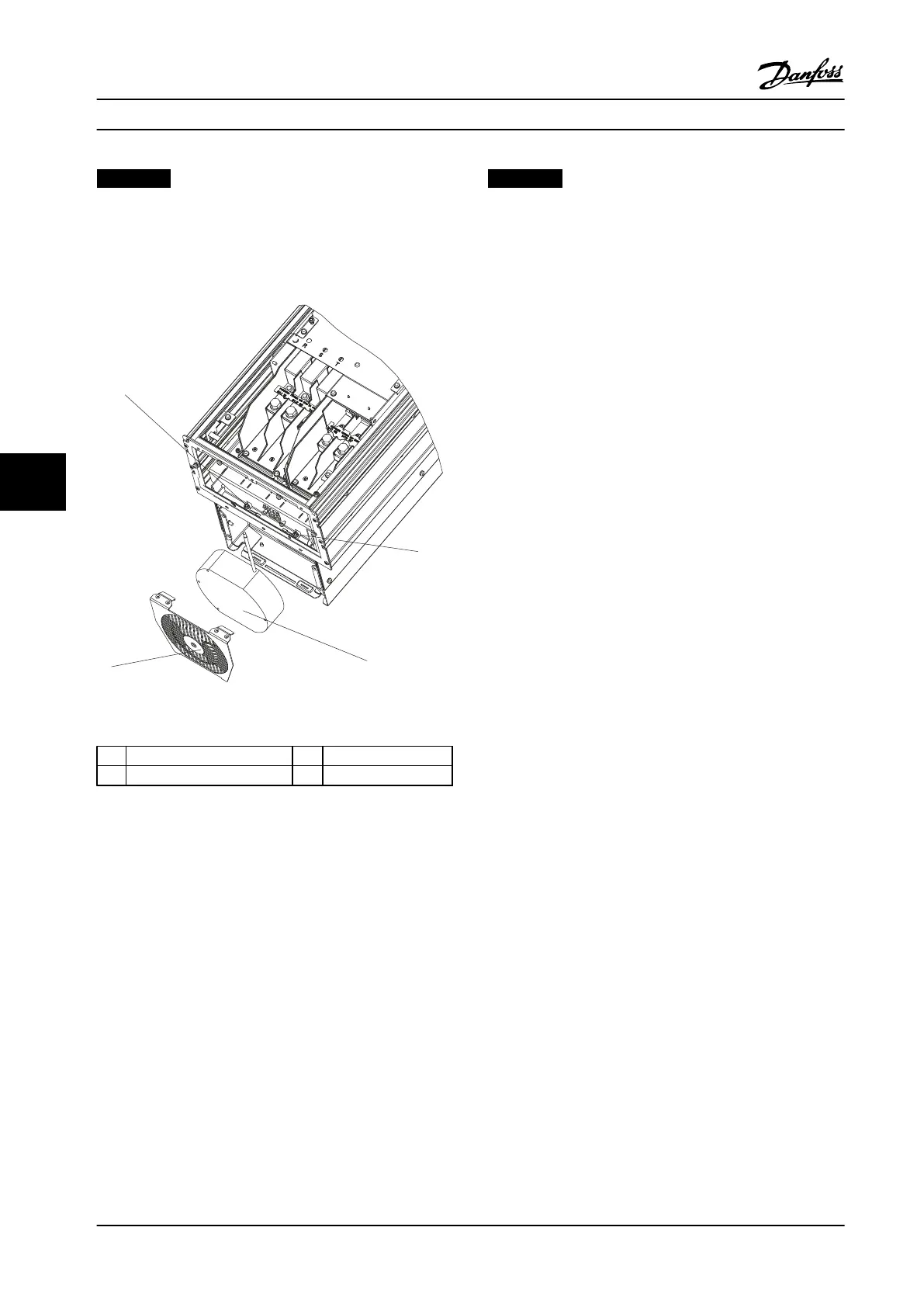
7.3.20 Heatsink Fan
Figure 7.10 Heatsink Fan
1 Captive screw (T25) 3 Fan
2 Captive screw (T25) 4 Fan cover
Table 7.10 Legend to Figure 7.10
1. Remove the fan cover by removing the two
captive screws (T25).
2. Unplug the fan electrical connector.
3. Remove the fan by pulling it free from the
mounting studs.
Reinstall in reverse order of this procedure and tighten
hardware according to chapter 1.7 General Torque
Tightening Values.
NOTICE!
If there is an options cabinet connected to the
adjustable frequency drive, see chapter 7.5.2 Removing
the Heatsink Fan with Options Cabinet Present for fan
removal instructions.
7.3.21 Door Fan: IP21 (NEMA 1) or IP54
(NEMA 12) Enclosures Only
1. Unplug the fan electrical connection.
2. Remove the door fan by removing four nuts (0.3
in [7 mm]), using an open-ended wrench.
Reinstall in reverse order of this procedure and tighten
hardware according to chapter 1.7 General Torque
Tightening Values.
7.3.22
Top Fan: (IP20 Enclosures Only)
1. Remove two screws (T25).
2. Slide the fan and bracket forward and pull them
out.
3. Unplug the inline connector (not shown).
Reinstall in reverse order of this procedure and tighten
hardware according to chapter 1.7 General Torque
Tightening Values.
Disassembly and Assembly In... Service Manual
102 Danfoss A/S © Rev. 2014-02-10 All rights reserved. MG94A222
77
 Loading...


