NOTICE!
Note that the IP21 (NEMA 1) and IP54 (NEMA 12)
versions have a different type and number of fasteners.
When installing the power card, ensure that the insulator
sheet is installed behind the power card.
Reinstall in reverse order of this procedure and tighten
hardware according to chapter 1.7 General Torque
Tightening Values.
7.4.4 Power Card
1. Remove the control card mounting plate in
accordance with chapter 7.4.2 Control Card and
Control Card Mounting Plate.
2. Unplug the power card connectors:
•
MK101
•
MK103
•
MK501
•
MK502
•
MK902
3. If customer connections are present, unplug
connectors MK500 and MK106.
4. Remove the five power card mounting screws
(T20).
5. Remove the two standoffs (0.3 in [8 mm]).
6. Remove the power card from the three plastic
standoffs.
7. Remove the current scaling card from the power
card by pushing in the retaining clips on the
standoffs. The scaling card controls signals
operating specifically with this adjustable
frequency drive. The scaling card is not part of
the replacement power card.
Reinstall in reverse order of this procedure and tighten
hardware according to chapter 1.7 General Torque
Tightening Values.
When installing the power card, ensure that the insulator
sheet is installed behind the power card.
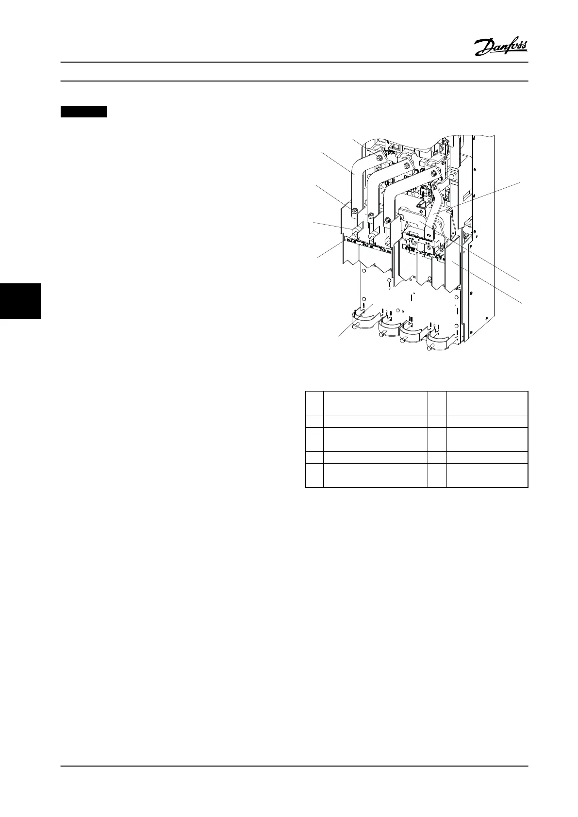
7.4.5
AC Input Bus Bars
Figure 7.13 Power Terminals
1 Top 0.5 in [13 mm] nut 6 Line power input
terminal
2 Brake bus bar (optional) 7 Fuse spacer
3 Motor terminal bus bar 8 Bottom 0.5 in [13 mm]
nut
4 Motor terminal block 9 Input power bus bar
5 Power terminal mounting
plate
Table 7.13 Legend to Figure 7.13
1. Remove the air baffle by removing the four
screws (T25) and two nuts (0.5 in [13 mm]).
2. The next step differs based on options. See
chapter 7.4.5.1 Electrical Fuses Only,
chapter 7.4.5.2 RFI Only, chapter 7.4.5.3 Fuses and
RFI, and chapter 7.4.5.4 No Options for more
details.
7.4.5.1
Electrical Fuses Only
1. Remove electrical fuses by removing six nuts (0.5
in [13 mm]), one at each end of each fuse.
2. Remove three nuts (0.5 in [13 mm]) at the top of
the bus bars. One per phase.
3. Remove the bus bars.
Reinstall in reverse order of this procedure and tighten
hardware according to chapter 1.7 General Torque
Tightening Values.
Disassembly and Assembly In...
Service Manual
104 Danfoss A/S © Rev. 2014-02-10 All rights reserved. MG94A222
77
 Loading...


