1. Remove the power card mounting plate in
accordance with chapter 7.4.3 Power Card
Mounting Plate.
2. Remove the power terminal mounting plate in
accordance with chapter 7.4.10 Power Terminal
Mounting Plate.
3. Remove the two screws (T40) at the top end of
the bus bar, one per bus bar.
4. From the other end of the bus bar, remove the
four nuts (0.4 in [10 mm]), two per bus bar.
Reinstall in reverse order of this procedure and tighten
hardware according to chapter 1.7 General Torque
Tightening Values.
7.4.18.2
With Optional Brake
624 mm (24.57 In)
333 mm (13.11 In)
378 mm(14.88 In)
322 mm (12.68 In)
9 mm (0.35 In)
9 mm (0.35 In)
mm (0.35 In)9
577 mm (22.72 In)
553 mm (21.77 In)
15 mm (0.60 In)
15 mm (0.60 In)
141 mm ( 5.55 In) 240 mm (9.45 In)
353 mm (13.90 In)
130BB814.10
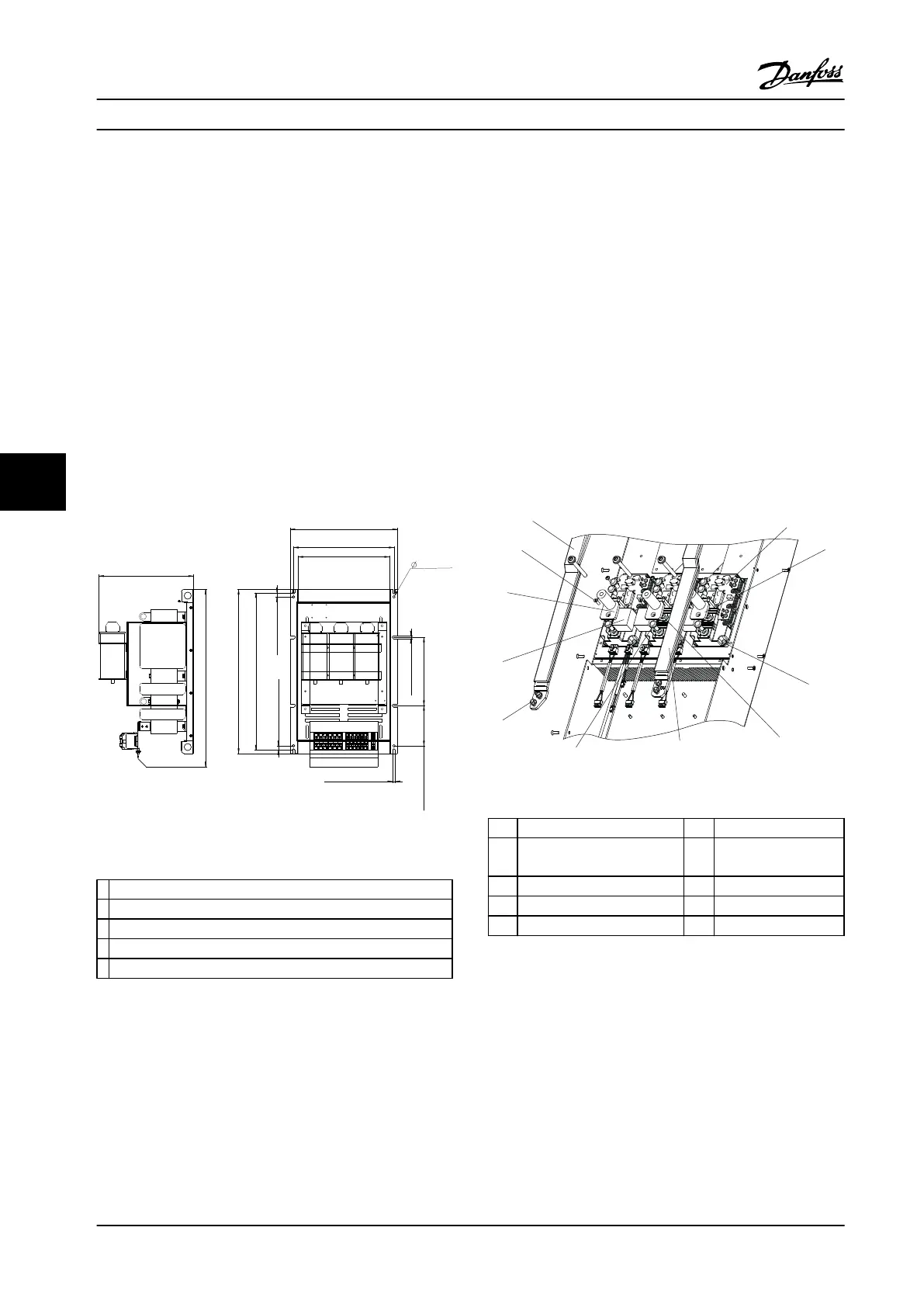
Figure 7.20 DC bus rails with brake option
1 (+) DC bus rail
2 (-) DC bus rail
3 T40 screw
4 13 mm nut
5 IGBT gate drive card
Table 7.20 Legend to Figure 7.20
1. Remove the power card mounting plate in
accordance with chapter 7.4.3 Power Card
Mounting Plate.
2. Remove the power terminal mounting plate in
accordance with chapter 7.4.10 Power Terminal
Mounting Plate.
3. Remove the 2 screws (T40) at the top end of the
bus bar, one per bus bar.
4. From the other end of the bus bar, remove the 4
nuts (10 mm), two per bus bar.
5. Remove 1 nut (13 mm) on the (+) DC bus rail,
near the center.
6. Remove 1 screw (T40) from the (-) DC bus rail,
near the center.
7. Remove the IGBT gate drive card in accordance
with chapter 7.4.14 IGBT Gate Drive Card.
Reinstall in reverse order of this procedure and tighten
hardware according to chapter 1.7 General Torque
Tightening Values.
7.4.19
IGBTs
Figure 7.21 IGBTs
1 (+) DC bus rail 6 (-) DC bus bar
2 IGBT 7 T40 IGBT terminal
screw
3 IGBT output bus bar 8 0.4 in [10 mm] nut
4 T25 IGBT mounting screw 9 Snubber capacitor
5 T40 IGBT terminal screw 10 T20 screw
Table 7.21 Legend to Figure 7.21
7.4.19.1
400 V AC Power Size
1. Remove the gate drive card in accordance with
chapter 7.4.14 IGBT Gate Drive Card.
2. Remove the balance/high frequency card in
accordance with chapter 7.4.13 Balance/High
Frequency Card.
3. Remove the DC bus rails in accordance with
chapter 7.4.18 DC Bus Rails.
Disassembly and Assembly In...
Service Manual
110 Danfoss A/S © Rev. 2014-02-10 All rights reserved. MG94A222
77
 Loading...


