5.2.5 Sources of EMI
Adjustable frequency drives utilize insulated-gate bipolar transistors (IGBTs) to provide an efficient and cost effective means
to create the pulse width modulated (PWM) output waveform necessary for accurate motor control. These devices rapidly
switch the fixed DC bus voltage creating a variable frequency, variable voltage PWM waveform. This high rate of voltage
change [dU/dt] is the primary source of the adjustable frequency drive generated EMI.
The high rate of voltage change caused by the IGBT switching creates high frequency EMI.
130BX137.10
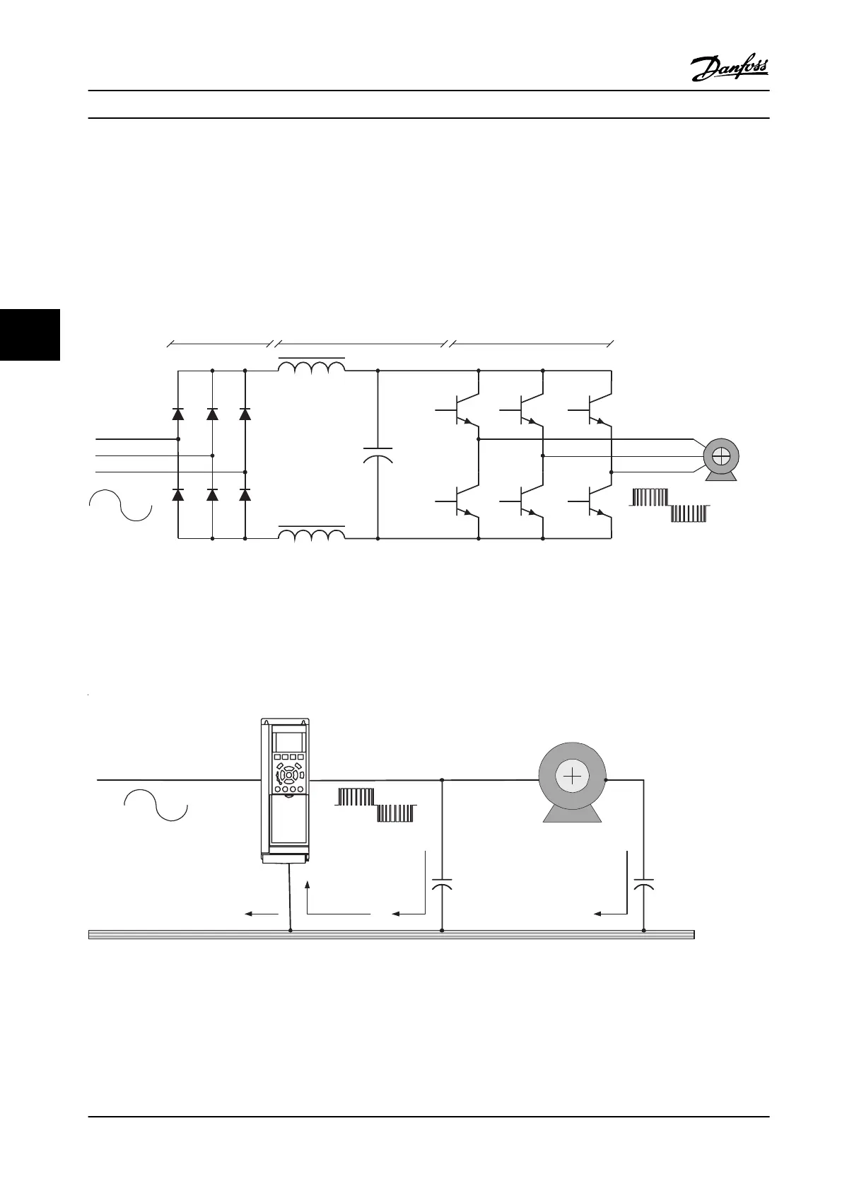
AC Line
Rectifier DC Bus Inverter
Motor
Filter reactor
IGBT
Filter capacitor
PWM waveformSine wave
Figure 5.1 Adjustable Frequency Drive Functionality Diagram
5.2.6
EMI Propagation
Adjustable frequency drive generated EMI is both conducted to the line power and radiated to nearby conductors. See
Figure 5.2.
130BX138.11
Motor Cable AC Line
Ground Potential 1 Potential 2 Potential 3
VFD
Motor
Stray capacitance Stray capacitance
Figure 5.2 Ground Currents
Adjustable Frequency Drive ... Service Manual
64 Danfoss A/S © Rev. 2014-02-10 All rights reserved. MG94A222
55
 Loading...


