Reinstall in reverse order of this procedure and tighten
hardware in accordance with chapter 1.7 General Torque
Tightening Values. See Figure 7.2 and Figure 7.3.
7.3.4 Power Card
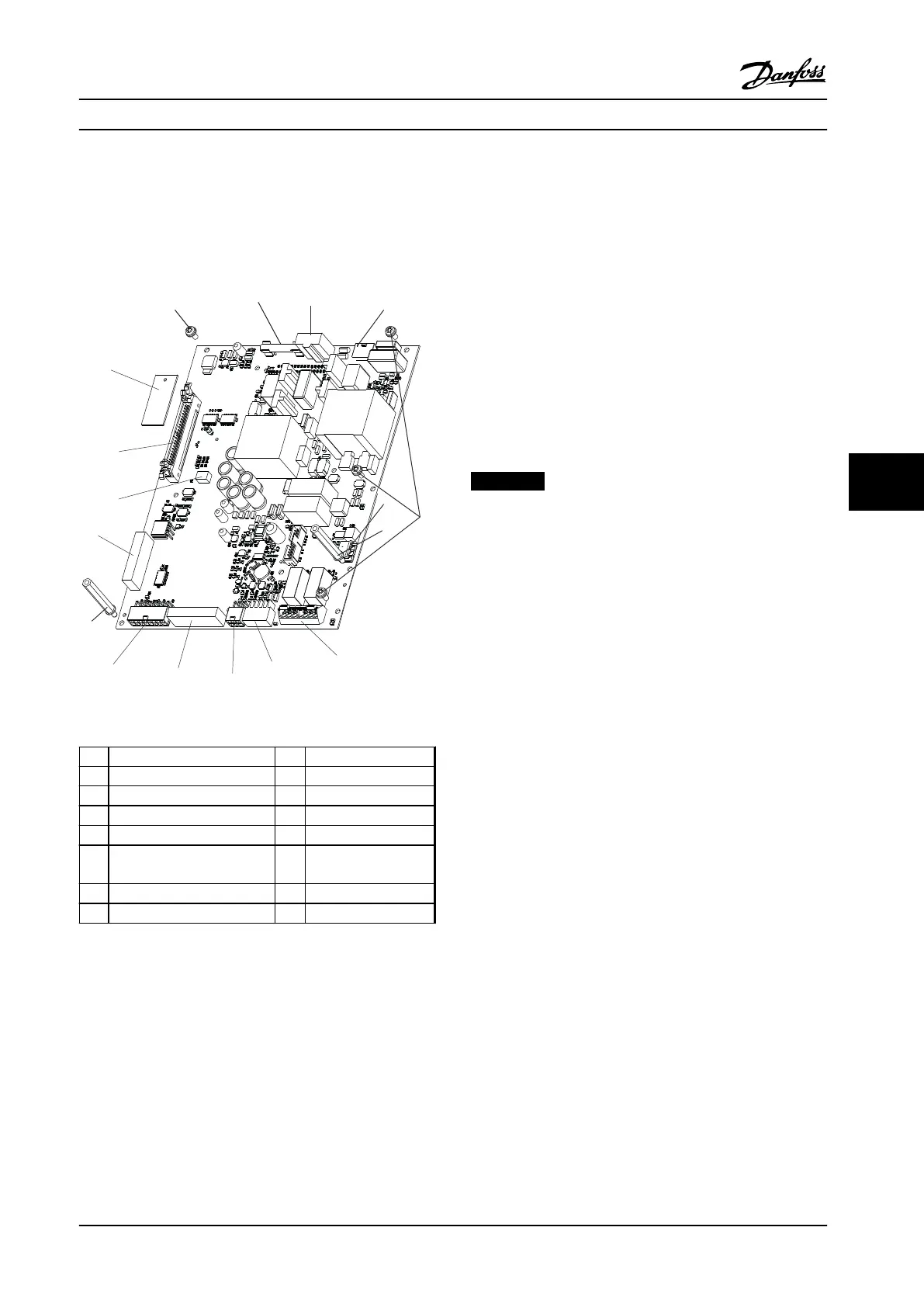
Figure 7.3 Power Card
1
Mounting screws (T20) 9 MK502
2 F901 10 MK103
3 MK901 11 MK101
4 MK902 12 MK104
5 MK106 13 MK100
6 Mounting standoffs (0.3 in [8
mm])
14 MK102
7 MK500 15 Current scaling card
8 MK501
Table 7.3 Legend to Figure 7.3
1. Remove the control card mounting plate in
accordance with chapter 7.3.2 Control Card and
Control Card Mounting Plate.
2. Unplug the power card connectors:
•
MK101
•
MK103
•
MK501
•
MK502
•
MK902
•
any additional customer-supplied wiring
at MK500 and MK106
3. Remove the five power card mounting screws
(T20).
4. Remove the two standoffs (0.3 in [8 mm]).
5. Remove the power card from the three plastic
standoffs.
6. Remove the current scaling card from the power
card by pushing in the retaining clips on the
standoffs. The scaling card controls signals
operating specifically with this adjustable
frequency drive and is not part of the
replacement power card.
NOTICE!
Keep this scaling card for future reinstallation of any
replacement power card.
Reinstall in reverse order of this procedure and tighten
hardware according to chapter 1.7 General Torque
Tightening Values. When installing the power card, ensure
that the insulator sheet is installed behind the power card.
See Figure 7.2
7.3.5
AC Input Bus Bars
See Figure 7.1 for location of bus bars.
7.3.5.1
Electrical Fuses Only
1. Remove electrical fuses by removing six nuts (0.5
in [13 mm]), one at each end of each fuse.
2. Remove three nuts (0.4 in [10 mm]) at the top of
of the bus bars. One per phase.
3. Remove the bus bars.
Reinstall in reverse order of this procedure and tighten
hardware according to chapter 1.7 General Torque
Tightening Values.
7.3.5.2
RFI Only
1. Remove three nuts (0.4 in [10 mm]) at the top of
the RFI filter, one per bus phase.
2. Remove six nuts (0.5 in [13 mm]) at the bottom
of the RFI filter, two per phase.
3. Remove four mounting screws (T20 thread-
cutting) connecting the RFI filter to the side
channels of the adjustable frequency drive.
Disassembly and Assembly In...
Service Manual
MG94A222 Danfoss A/S © Rev. 2014-02-10 All rights reserved. 93
7 7
 Loading...


