Reinstall in reverse order of this procedure and tighten
hardware according to chapter 1.7 General Torque
Tightening Values.
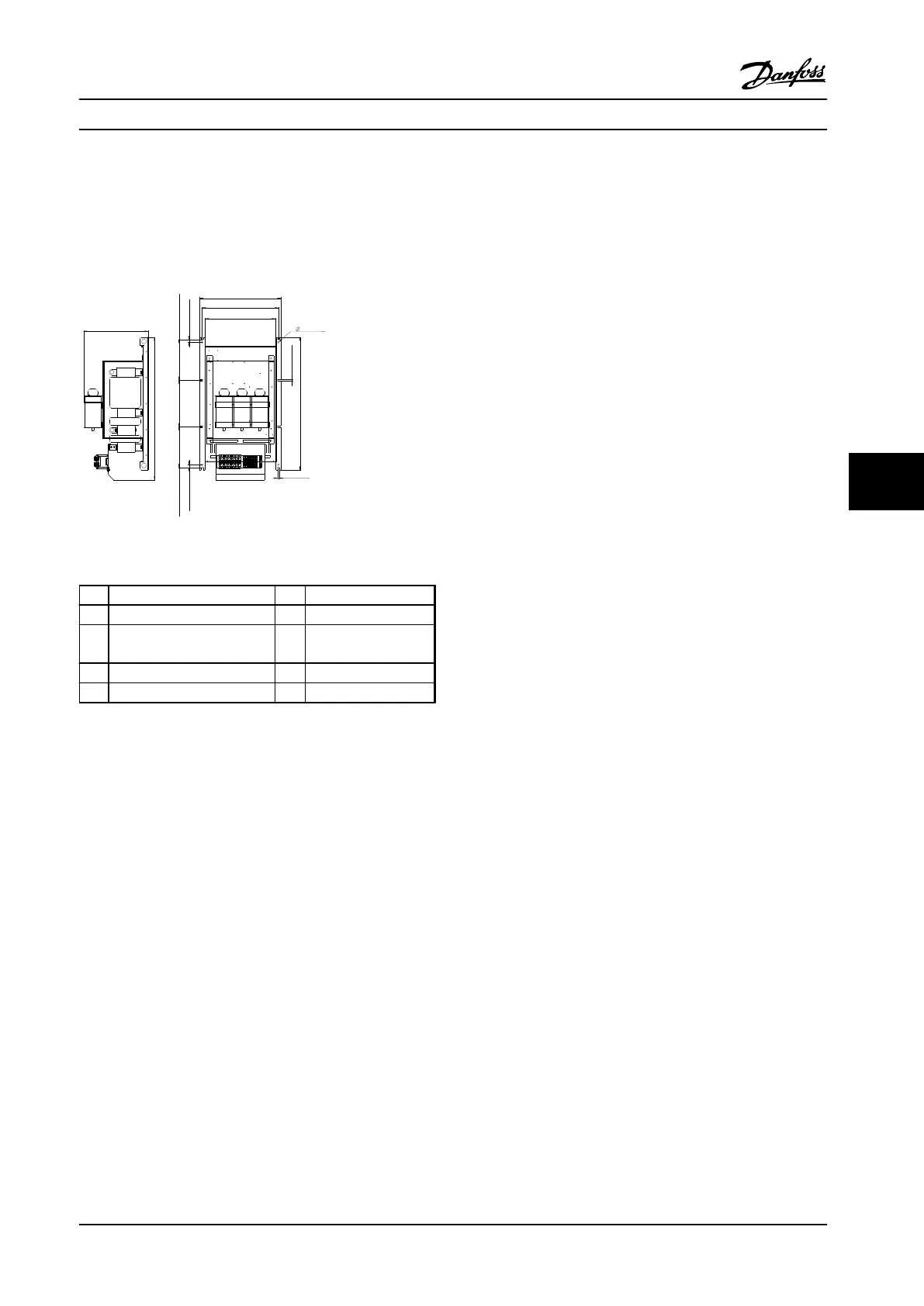
7.4.20.2 690 V AC Power Size
737 mm (29.02 In)
332 mm (13.07 In)
210.5 mm (8.29 In) 240 mm (9.45 In) 210.5 MM (8.29 In)
15 mm (0.60 In)15 mm (0.60 In)
393 mm (15.47 In)
362 mm (14.25 In)
418 mm (16.46 In)
685 mm (26.97 In)
9 mm (0.35 In)
mm (0.35 In)9
9 mm (0.35 In)
130BB815.10
Figure 7.23 DC Capacitors for 690 V AC units
1 Balance/High frequency card 6 Mylar insulator
2 Capacitor bank cover 7 DC centre plates
3 (+) DC plate 8 Capacitor locking
panel
4 Mylar Insulator 9 DC capacitors
5 (-) DC plate
Table 7.23 Legend to Figure 7.23
1. Remove the gate drive card in accordance with
chapter 7.4.14 IGBT Gate Drive Card.
2. Remove the balance/high frequency card in
accordance with chapter 7.4.13 Balance/High
Frequency Card.
3. Remove the DC bus rails in accordance with
chapter 7.4.18 DC Bus Rails.
4. Remove the Mylar cover from the capacitor bank.
5. Remove the IGBT output bus bars by removing 3
screws (T20 thread forming), one per bus bar, and
6 screws (T40), two per bus bar.
6. Remove the snubber capacitors, one from each
IGBT module, by removing 2 screws (T40).
7. Remove the (+)DC plate by removing 2 screws
(T20 thread forming), and screws (T25)
connecting the plate to the positive terminals of
capacitors 4, 8, 10, and 12. Number of T25 screws
varies based on the size of the frequency
converter.
8. Remove the Mylar insulator between the (+)DC
plate and the (-)DC plate. The screws connecting
(-)DC plate and the two DC centre plates to the
capacitors may have to be removed to remove
the insulator.
9. Remove the (-)DC plate by removing 1 standoff (8
mm) connecting the plate to the negative
terminal of capacitor 2, and screws (T25)
connecting the plate to the negative terminals of
capacitors 1, 5 and 6. Number of T25 screws
varies based on the size of the frequency
converter.
10. Remove the Mylar insulator between the (-)DC
plate and the two DC centre plates. The screws
connecting the two DC centre plates to the
capacitors may have to be removed to remove
the insulator.
11. Remove DC centre plate 1 by removing:
•
1 standoff (8 mm) connecting the plate
to the positive terminal of capacitor 7
•
Screws (T25) connecting the plate to the
negative terminal of capacitors 4, 8, 10
and 12
•
Screws (T25) connecting the plate to the
positive terminals of capacitors 3, 9 and
11. Number of T25 screws varies based
on the size of the frequency converter
12. Remove DC centre plate 2 by removing:
•
1 standoff (8 mm) connecting the plate
to the positive terminal of capacitor 6
•
Screws (T25) connecting the plate to the
negative terminal of capacitors 3, 7, 9
and 11
•
Screws (T25) connecting the plate to the
positive terminals of capacitors 1, 2 and
5. Number of T25 screws varies based
on the size of the frequency converte
13. Remove the capacitor locking panel by removing
10 screws (T25 thread forming).
Reinstall in reverse order of this procedure and tighten
hardware according to chapter 1.7 General Torque
Tightening Values.
Disassembly and Assembly In...
Service Manual
MG94A222 Danfoss A/S © Rev. 2014-02-10 All rights reserved. 113
7 7
 Loading...


