Home
Danfoss
DC Drives
VLT FC Series
Danfoss VLT FC Series Service Guide
5
of 1
of 1 rating
370 pages
Give review
Manual
Specs
To Next Page
To Next Page
To Previous Page
To Previous Page
Loading...
e30bg393.10
1
2
3
4
5
6
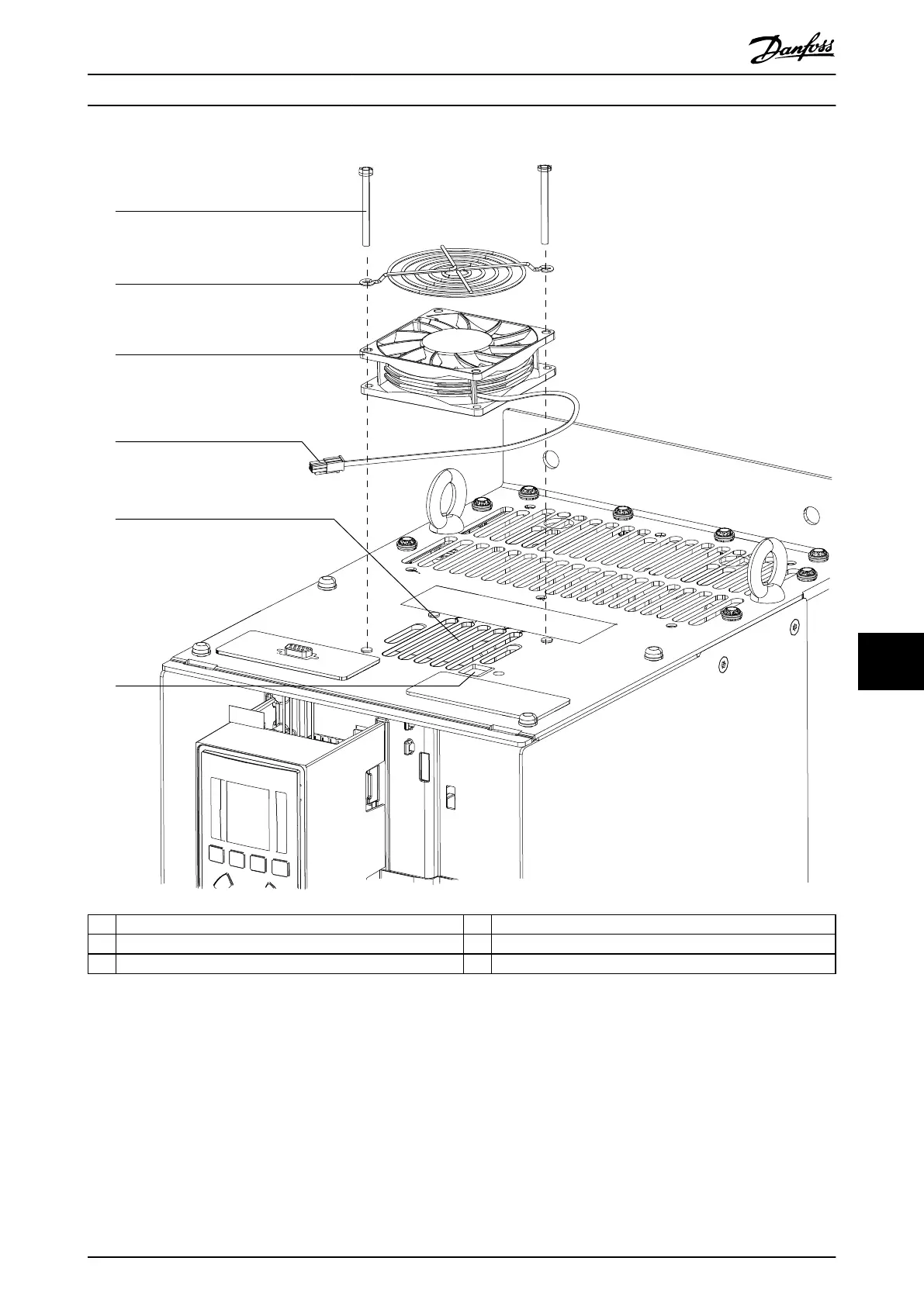
1
Screw
(
T25)
4
T
op
fan
cable
and
connector
2
T
op
fan
grill
5
T
op
vent
3
T
op
fan
6
Cable
access
hole
Illustration
10.28
T
op
Fan
with
Grill
D1h/D3h/D5h/D6h/J8 Drive Di...
Ser
vice Guide
MG94A502
Danfoss A/S © 02/2019 All rights reserved.
177
10
10
178
180
Table of Contents
Default Chapter
3
Table of Contents
3
1 Introduction
11
Purpose of this Guide
11
Additional Resources
11
Abbreviations and Acronyms
12
Conventions
13
Document Version
13
Approvals and Certifications
13
Disposal
13
2 Safety
14
Introduction
14
Safety Symbols
14
Qualified Personnel
14
Safety Precautions
14
Electrostatic Discharge
16
3 Product Overview
17
Introduction
17
Tools Required
17
Service Report
17
Enclosure Size Identification
18
Enclosure Size Definitions
19
Product Views
24
Exploded View of D1H/D3H/D5H/D6H/J8 Drive
24
Exploded View of D2H/D4H/D7H/D8H/J9 Drive
25
Exploded View of Multi-Drive System
26
View of Control Shelf
27
Exploded View of Parallel Drive Module
28
View of Parallel Drive Module
29
Exploded View of E-Sized Unit
30
Product Options
31
4 Operator Interface and Drive Control
32
Introduction
32
Local Control Panel
32
Layout
32
Menus
33
Parameter Settings
35
Uploading and Downloading Parameter Settings
35
Restoring Factory Default Settings
35
Status Messages
36
Status Message Definitions
36
Service Functions
39
Drive Inputs and Outputs
40
Input Signals
40
Output Signals
40
Control Supply
41
Control Terminals
41
Control Terminal Functions
42
Shielded Cable Grounding
43
5 Internal Drive Operation
44
Introduction
44
Description of Operation
44
Logic Section
46
Logic-To-Power Interface
46
Power Section
47
Sequence of Operation
48
Rectifier Section
48
Intermediate Section
51
Inverter Section
54
Brake Option
57
Cooling Fans
59
Fan Speed Control
59
Load Sharing and Regen
60
Specific Power Card Connections
61
6 Troubleshooting
62
Troubleshooting Tips
62
Exterior Fault Troubleshooting
62
Fault Symptom Troubleshooting
62
Visual Inspection
63
Fault Symptoms
64
No Display
64
Intermittent Display
64
Motor Does Not Run
64
Incorrect Motor Operation
64
Alarms and Warnings
65
Overview of Alarms and Warnings
65
Alarm/Warning Identification Tables
66
Alarm and Warning Definitions
70
7 Drive and Motor Applications
82
Torque Limit, Current Limit, and Unstable Motor Operation
82
Overvoltage Trips
83
Mains Phase Loss Trips
83
Control Logic Problems
84
Programming Problems
84
Motor Load Problems
84
Internal Drive Problems
85
Overtemperature Faults
85
Current Sensor Faults
85
Electromagnetic Compatibility
85
Effects of EMI
85
EMI Signal and Power Wiring
86
Sources of EMI
86
EMI Propagation
86
Preventive Measures
89
8 Test Procedures
91
Introduction
91
Tools Required
92
Special Test Equipment
92
Signal Test Board
92
Metering Tools
93
Test Preparations
93
Preparations for Parallel Drive Systems
94
Access to Testing Connection Points
94
Card Connectors
95
Power Card in D-Sized Drives
96
Power Card in E-Sized Drives
97
MDCIC in Parallel Drive Systems
98
Fan Power Card in E-Sized Drives
99
Gate Drive Card in D-Sized Drives
100
Gate Drive Card in E-Sized Drives
101
Static Test Procedures
102
Rectifier Circuits Test
102
Inverter Section Tests
103
Brake IGBT Test
103
Intermediate Section Tests
104
IGBT Temperature Sensor Test
104
Gate Resistor Test
105
Mains Fuse/DC Fuse Test
105
Disconnect Test
105
Circuit Breaker Test
106
Contactor Test
106
Dynamic Test Procedures
107
No Display Test
109
Input Voltage Test
109
Basic Control Card Voltage Test
109
DC Bus Voltage Test
109
Switch Mode Power Supply Test
110
Input Imbalance of Supply Voltage Test
110
Input Waveform Test
111
Input SCR Test
111
Output Imbalance of Motor Voltage and Current
112
IGBT Switching Test
113
IGBT Gate Drive Signals Test
114
Current Sensors Test
116
Fan Tests
118
Input Terminal Signal Tests
119
After-Repair Tests
120
After-Repair Tests for D-Sized and E-Sized Drives
121
After-Repair Tests for Parallel Drive Systems
121
9 Special Test Equipment
122
Split Bus Power Supply
122
Overview
122
Split Bus Power Supply Diagrams
122
Split Bus Power Supply Connection
124
Parallel Drive Module Service Kit
124
Overview
124
Split Bus Power Supply and Parallel Drive Modules
126
After-Test Installation of Parallel Drive Modules
127
Programming the Parallel Drive Module
127
Service Kit Troubleshooting
127
Signal Test Board
127
Signal Test Board Pin Outs
128
10 D1H/D3H/D5H/D6H/J8 Drive Disassembly and Assembly
131
Before Proceeding
131
D1H/D3H/D5H/D6H/J8 Disassembly and Assembly
132
General Information
132
Control Card and Control Card Mounting Plate
132
Power Card Mounting Plate
134
Power Card
136
AC Input Busbars
138
Mains Input Terminal Block
140
Motor Terminal Block
142
Brake Terminal Block (Optional)
143
Power Terminal Mounting Plate
143
Mixing Fan
144
Current Sensors
146
Balance/High Frequency Card
148
DC Bus Rails
149
Inrush Card
150
SCR Input Busbars
152
Scrs
152
Gate Drive Card
154
Brake IGBT Module
154
Igbts
156
Standard DC Capacitors
158
Standard DC Capacitor Bank Layouts
164
Twistlock DC Capacitors
166
Twistlock DC Capacitor Bank Layouts
170
Heat Sink Fan
172
Door Fan
175
Top Fan
177
D5H/D6H Disassembly and Assembly
180
Accessing the Heat Sink Fan in D5H/D6H Drives
180
Removing the Drive from the Extended Options Cabinet
182
Contactor
184
Disconnect
184
Heat Sink Access Panel
186
Removing the Heat Sink Access Panel
186
11 D2H/D4H/D7H/D8H/J9 Unit Disassembly and Assembly
188
Before Proceeding
188
D2H/D4H/D7H/D8H/J9 Disassembly and Assembly
189
General Information
189
Control Card and Control Card Mounting Plate
190
Power Card Mounting Plate
192
Power Card
192
AC Input Busbars
194
Mains Input Terminal Block
196
EMC Shield
198
Brake Terminal Block (Optional)
198
Motor Terminal Block
199
Mixing Fan
200
Power Terminal Mounting Plate
202
Current Sensors
203
Balance/High Frequency Card
205
Gate Drive Card
207
Inrush Card
209
SCR Input Busbars
211
Scrs
211
DC Bus Rails
213
Igbts
216
Standard DC Capacitors
218
Standard DC Capacitor Bank Layouts
222
Twistlock DC Capacitors
226
Twistlock DC Capacitor Bank Layouts
230
Brake IGBT Module
232
Heat Sink Fan
234
Door Fan
237
Top Fan
239
D7H/D8H Disassembly and Assembly
242
Removing the Drive from the Extended Options Cabinet
242
Accessing the Heat Sink Fan in D7H/D8H Drives
242
Contactor
244
Disconnect
244
Heat Sink Access Panel
246
Removing the Heat Sink Access Panel
246
12 Da2/Db2/Da4/Db4 Parallel System Disassembly and Assembly
248
Before Proceeding
248
Lifting the Unit
249
Parallel Drive System Disassembly and Assembly
251
Removing the Control Shelf
251
Removing a Drive Module
252
Installing the Drive Modules
253
Installing the Control Shelf
255
Parallel Drive Module Disassembly and Assembly
257
General Information
257
Blank Mounting Plate
259
13 E1H-E4H Drive Disassembly and Assembly
261
Before Proceeding
261
E1H-E4H Disassembly and Assembly
262
General Information
262
Control Card and Control Card Mounting Plate
263
Power Card Mounting Plate
265
Power Card
267
Fan Power Card
269
Inrush Card
271
Inrush Card Frame and Rectifier Bus Plates
273
Scr/Diode Modules
275
Input Plate with Busbars
277
Split Input Plate with Options
279
Input Plate Mixing Fan
281
Power Card Mixing Fan
283
Gate Drive Card Mounting Plate
285
Gate Drive Card
287
Current Sensors
289
Motor Busbar Assembly
291
Balance/High Frequency Card
293
Heat Sink Fan
295
DC Snubber Capacitors
297
Twistlock DC Capacitors
299
DC Capacitor Layouts
303
Igbts
307
Door Fan
309
Top Fan
311
Vertical Brake Busbars
313
Horizontal Brake Busbars
315
DC Bus Rails
319
14 Product Specifications
321
Fastener Torque Ratings
321
General Torque Tightening Values
321
Unique Torque Values in E1H-E4H Drives
322
DC Voltage Levels
323
Warning and Alarm Trips Points
323
15 Spare Parts
325
Using the Drive Configurator Tool
325
Spare Parts Lists
325
Recommended Current Scaling Cards
326
16 Block Diagrams
358
Index
364
Other manuals for Danfoss VLT FC Series
Operating Instructions
64 pages
Operating Guide
26 pages
Instructions
11 pages
Installation Guide
12 pages
Installation Instructions
6 pages
5
Based on 1 rating
Ask a question
Give review
Questions and Answers:
Need help?
Do you have a question about the Danfoss VLT FC Series and is the answer not in the manual?
Ask a question
Danfoss VLT FC Series Specifications
General
Brand
Danfoss
Model
VLT FC Series
Category
DC Drives
Language
English
Related product manuals
Danfoss VLT FC 103
182 pages
Danfoss vlt FC 102
188 pages
Danfoss VLT FC 302 N132
182 pages
Danfoss VLT FC 302 N200
182 pages
Danfoss VLT AQUA FC 202
148 pages
Danfoss VLT FC 102 N250
182 pages
Danfoss VLT FC 302 N450
182 pages
Danfoss VLT FC 51 Series
83 pages
Danfoss VLT FC 100 Series
82 pages
Danfoss VLT Midi Drive FC 280
82 pages
Danfoss VLT AQUA Drive FC 202
206 pages
Danfoss VLT Micro Drive FC 51
36 pages
 Loading...