A. Display area
Each display readout has a parameter associated with it.
Refer to Illustration 4.1. The information shown on the LCP
can be customized for user application by selecting
options in the Quick Menus Q1 My Personal Menu.
Callout Parameter number Default setting
A1.1 0-20 Refer to Table 4.6 –
Table 4.8
A1.2 0-21
A1.3 0-22
A2 0-23
A3 0-24
Table 4.1 LCP Display Area
B. Menu keys
Menu keys are used to access the menu for setting up
parameters, toggling through status display modes during
normal operation, and viewing fault log data.
Callout Key Function
B1 Status Shows operational information.
B2 Quick Menu Allows access to parameters for initial
set-up instructions. Also provides
detailed application steps. Refer
to chapter 4.2.2.1 Quick Menu Mode.
B3 Main Menu Allows access to all parameters. Refer to
chapter 4.2.2.6 Main Menu Mode.
B4 Alarm Log Shows a list of current warnings and the
last 10 alarms.
Table 4.2 LCP Menu Keys
C. Navigation keys
Navigation keys are used for programming functions and
moving the display cursor. The navigation keys also
provide speed control in local (hand) operation. Adjust
display brightness by pressing [Status] and [
▲
]/[
▼
] keys.
Callout Key Function
C1 Back Reverts to the previous step or list in the
menu structure.
C2 Cancel Cancels the last change or command as
long as the display mode has not changed.
C3 Info Shows a denition of the function being
shown.
C4 OK Accesses parameter groups or enables an
option.
C5
▲
▼
◄ ►
Moves between items in the menu.
Table 4.3 LCP Navigation Keys
D. Indicator lights
Indicator lights are used to identify the drive status and to
provide a visual notication of warning or fault conditions.
Callout Indicator Indicator
light
Function
D1 On Green Activates when the drive receives
power from the mains voltage or
a 24 V external supply.
D2 Warn. Yellow Activates when warning
conditions are active. Text
appears in the display area
identifying the problem.
D3 Alarm Red Activates during a fault
condition. Text appears in the
display area identifying the
problem.
Table 4.4 LCP Indicator Lights
E. Operation keys and reset
The operation keys are found toward the bottom of the
local control panel.
Callout Key Function
E1 [Hand On] Starts the drive in local control. An
external stop signal by control input or
serial communication overrides the local
hand on.
E2 O Stops the motor but does not remove
power to the drive.
E3 Auto On Puts the system in remote operational
mode so it can respond to an external
start command by control terminals or
serial communication.
E4 Reset Resets the drive manually after a fault has
been cleared.
Table 4.5 LCP Operation Keys and Reset
4.2.2 Menus
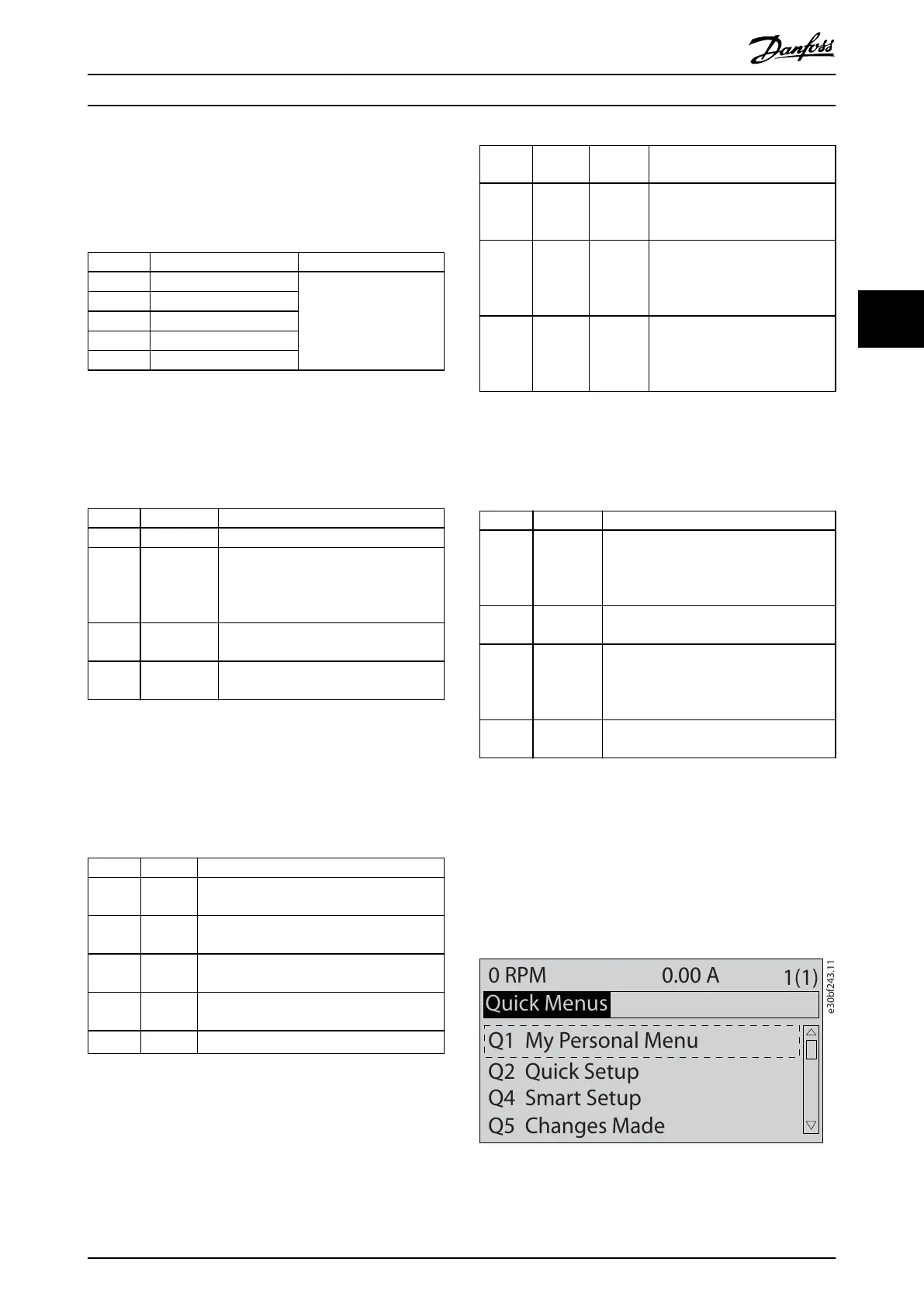
4.2.2.1 Quick Menu Mode
The LCP provides access to parameters via the Quick
Menus. To list the quick menu options, press [Quick
Menus].
Illustration 4.2 Quick Menu View
Operator Interface and Driv... Service Guide
MG94A502 Danfoss A/S © 02/2019 All rights reserved. 31
4 4
 Loading...